RF splitters combiners, couplers, and hybrids are a group of components used in many RF applications.
- RF combiners, splitters, couplers, and hybrids are circuit elements that are used in many RF applications to split, combine or sample RF power.
- Generally, they are passive devices that can be used within RF circuits, or even externally.
- All the RF combiners, splitters, couplers, and hybrids are very similar.
RF Combiners / Splitters:
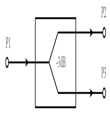
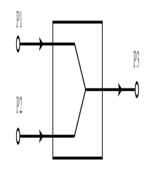
- RF power combiners and RF splitters are the same items. The same circuits can be used to combine and split RF power, the only difference is that RF power is applied to one port and extracted from the other.

- In the RF splitter, and for the RF combiner, power is applied in the opposite direction.
- The RF power splitters and combiners are used to split a single RF line into more than one line and divide the power.

- The combiners are used to combine more than one feed line into a single one.
- There are two types of RF power splitters.
1. Resistive Power Splitters:
- These power splitters and combiners use resistors.
- Since they can maintain the characteristic impedance of the system, the use of resistors introduces loss above that of the minimum caused by any splitting action.
- They are cheap and easy to make.
2. Hybrid Power Splitters:
- It is use transformers and can provide low levels of loss.
- While there are some physical losses in the transformer, the major “loss” that arises from the splitting process as the same signal is shared between several outputs.
RF Couplers:
- It separates signals based on the direction of signal propagation.
- The RF coupler is used to unequally split the signal flowing in the mainline and to fully pass the signal flowing in the opposite direction.
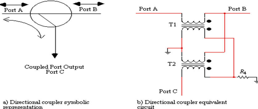
- The portion of the signal flowing into port A will appear at Port C. Likewise any signal flowing into port C will be coupled fully to port A.
- Although ports B and C are isolated in that any signal flowing into port B will not appear at port C but will feed through to port A.
- The generic RF directional coupler symbol, shown in Figure(a), is usually realized by two transformers connected as shown in Figure(b).
- This type is impedance less, in that they become 50 ohms or 75 ohms, directional couplers simply by matching all ports to either 50 ohms or 75 ohms, respectively.

RF Hybrid:
- Several circuits are referred to as hybrids.
- They are based on transformers, and such as RF splitters or RF combiners may be referred to as hybrids when they use transformer technology rather than just resistive technology.
- This gives many advantages, dependent upon the actual circuit, but one of the main ones is that hybrids do not have the resistive losses of the resistive ones.
