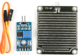
- A rain sensor, sometimes known as a rain switch, is a switching device that is actuated by rain; it is a straightforward circuit that recognizes rain and generates an alert.
- Below is a picture of the rain sensor module/board. This board uses the resistance concept and has nickel-coated lines. A rain board that detects rain and a control module that compares the analog value and turns it into a digital value make up this device.

How does a Raindrops Detection Sensor Module work?
- A board with lines of nickel coated on it serves as the basic structure of a raindrop sensor. It operates according to the idea of resistance. when there isn’t a drop of rain on the boat. Following V=IR, a high resistance results in a high voltage. Because water conducts electricity and connects nickel lines in parallel when it rains, the resistance is lowered, and the voltage drop across it is also reduced.
Copper Padding
- The rain sensor module’s operation is simple and uncomplicated. The sensor is made up of several exposed copper pathways, each of which serves as a variable resistor whose resistance changes in response to the amount of water present on its surface. They are typically separated by a waterway rather than being joined. The amount of water has an inverse relationship with this resistance. The conductivity of the rain pads will be improved and result in decreased resistance the more water there is on the surface. The sensor generates an output voltage that it uses to detect whether or not it is raining.
Sensor Unit
- The raindrop sensor module, which can be attached to any microcontroller, is made up of a control sensor and a rain-sensing pad. The module output voltage is provided via the analog output pin and is determined by the resistance of the sensor pad. The identical signal is also sent to the LM393 high-precision comparator, where it is converted into digital form and made available at the TTL digital output pin.
Circuit of Control
- A potentiometer that controls the output of the digital pin is also a feature of the raindrop module. This potentiometer should be calibrated for reliable readings. The input analog voltage is applied to the non-inverting side of the LM393 comparator while the potentiometer is connected to the inverting end of the comparator to set the reference or threshold voltage. Both voltages are compared by the relevant comparator. With the help of two conditions, the output is determined. The comparator displays a high state if the input voltage is greater than the reference value.
LED Indication
- The comparator output will be low if the threshold voltage is higher than the applied voltage. In addition to these, the module contains a status LED and a power LED. When the module is powered on, the power LED illuminates, and the status LED lights show the condition of the digital output pins.
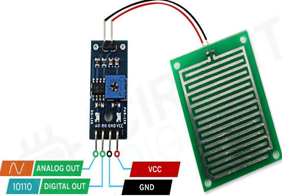
Pin Configuration of Raindrops Detection Sensor Module
The pin description of the Raindrops Detection Sensor Module is given below.
-

Pin Configuration of Raindrops Detection Sensor Module
- VCC – Connects supply voltage- 5V.
- GND – Connected to ground.
- D0 – Digital pin to get digital output.
- A0 – Analog pin to get analog output.
Features and Specifications of Raindrops Detection Sensor Module
- Adopts high-quality RF-04 double-sided material.
- Area: 5cm x 4cm nickel plate on side.
- Anti-oxidation, and anti-conductivity, with long use time.
- Comparator output signal clean waveform is good, driving ability, over 15mA.
- Potentiometer adjusts the sensitivity.
- Working voltage 5V.
- Output format: Digital switching output (0 and 1) and analog voltage output AO.
- With bolt holes for easy installation.
- Small board PCB size: 3.2cm x 1.4cm.
- Uses a wide voltage LM393 comparator.
Applications of Raindrops Detection Sensor Module
- Automatic windshield wipers.
- Smart Agriculture.
- Home-Automation.
- On the roof of houses and offices to take necessary action during rain.
- Weather monitoring.
