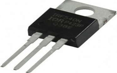
- IRF540 is an N-Channel driven MOSFET that is employed in both amplification and extremely quick switching applications. It runs in the mode of improvement. It is far more sensitive than a typical transistor because of its very high input impedance. It is used in a wide variety of everyday applications, including switching regulators, relay drivers, switching converters, motor drivers, high-speed power switching drivers, etc. You should also look at different MOSFETs and evaluate their performance against IRF540.
- A cutting-edge HEXFET power MOSFET from International Rectifier, the IRF540N, employs extremely intricate processing techniques to provide extremely low on-resistance for each “Si” area. The primary benefits are the quick switching times, sturdy device construction, and provision of an extremely effective, dependable device to the designer for use in various applications.
- Industrial applications with a commercial component are frequently chosen to use the TO-220 package. This package will be widely accepted throughout the industry since it costs less to produce and has a lower thermal resistance.
- This IC is ideal for a variety of electronic applications because of its versatility in switching voltage and current.
- The IRF540 MOSFET has a fairly straightforward operating system and has three terminals: the source, drain, and gate. Both the transistor’s drain and gate terminals will be shorted as soon as a signal is applied to its gate terminal. Only when the Drain & the Gate are shorted can we obtain the desired outcomes; else, it will produce extraneous outputs.

IRF540N MOSFET Pin Configuration
- The following pins are included in the IRF540N MOSFET’s pin arrangement. This MOSFET IC has three pins, each of which is described below along with its function. The pin diagram and symbol for the IRF540N MOSFET are displayed below.
- Pin1 (Source): Current supplies out throughout the Source terminal.
- Pin2 (Gate): This pin controls the MOSFET biasing.
- Pin3 (Drain): Current supplies throughout the Drain terminal.
Working of IRF540N MOSFET
- Below is a circuit diagram for a straightforward two-lamp flasher that uses an IRF540N MOSFET. This circuit uses an as table multi vibrator, making it a preferable option if we want a lap flasher with high power.
- To assemble this circuit, you’ll need two 470K resistors, two IRF540N MOSFETs, a 12V battery, two 10W bulbs, and two 1uF transistors.
- Here, a MOSFET is used to construct a straightforward flashing light circuit. LED screens are quite easy to construct for this circuit. However, using high-wattage lamps or light bulbs will make this exceedingly challenging.
- This circuit employs a 12-volt battery, however, two IRF540N MOSFETs must be added to boost the current flowing to the load. With this circuit, we can power lamps that are up to 10A/100 watts. To make the lamp flash simultaneously in the circuit above, R1=R2 and C1=C2 will have identical values.
Applications of IRF540N MOSFET
- IRF540N N-Channel MOSFET IC is capable of driving loads up to 23A.
- It is often used for logic switching with many microcontrollers, including Arduino.
- This MOSFET can control the speed of motors and light dimmers since it has good switching properties.
- This MOSFET is suitable for switching applications since it can use some logic-level devices to exhaust its maximum current.
- Devices with high power bases are switched using it.
- Utilized to regulate the speed of motors.
- LED dimmers and flashers.
- Circuits for inverters/converters.
- The high current SMPS, inverter circuits with tiny ferrite or iron core, power amplifiers, buck & boost converters, robotics, etc. are only a few examples of applications for this MOSFET IC that are based on high power DC switching.