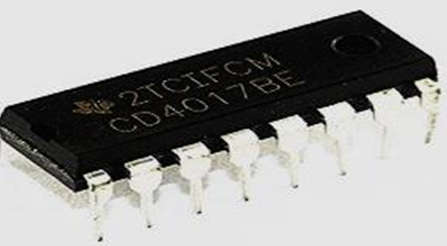
- CMOS Decade counter, the CD4017 IC is utilized in low-range counting applications. The circuit using an IC 4017 will save space on the circuit board and the time required to create the circuit. This IC will count from 0 to 10. The Johnson 10-stage decade counter is comparable to this decade counter.
- When creating the 10 LED-based circuits that power the light for beginners, this CMOS IC is typically employed. Since it counts up to 10 and has 10 distinct outputs, it is one of the most adaptable counters. The decoder and the counter are both included in this IC.

Pin Configuration of IC 4017
- A CMOS decade counter, such as the 4017 IC, has a five-stage Johnson counter and ten decoded outputs for counting up to ten decimals. This integrated circuit can be used in a variety of counter circuits, including an LED chaser light and a non-contact circuit with an AC detector. This IC has 16 pins, 10 of which are output pins. This IC counts every positive edge input provided at the CLK input that is otherwise increasing.
- The output here starts at ‘0’ and progresses to ‘9’. When it reaches, the output will count at ‘9,’ and it will then repeat from 0 and continue this revolution, much like a ring counter. On each count from 0 to 9, one output pin can be high while the remaining output remains low; only one o/p will be high at a time.
- For example, if the count is currently three, the output at pin-7 will be high, while the remaining pins will be low. If two square wave cycles are applied to the clock input, the output will shift to output 4 on the positive edge of the primary cycle, changing output-4 to high and output-3 to low.
- The condition now remains until the next cycle’s positive edge arrives, at which point the o/p moves to Pin 1 or output 5 and maintains this condition. The internal structure of the ic 4017 is depicted below.
![]()
It has 16 pins, and the functions of each pin are as follows
- Pin-1 is the fifth output. When the counter reaches 5 counts, it goes up.
- Pin-2 is output number one. When the counter reads 0 counts, it goes high.
- Pin-3 is the 0th output. When the counter reads 0 counts, it goes high.
- Pin-4 is output number two. When the counter reads two counts, it goes high.
- Pin-5 is the output pin. When the counter reads 6 counts, it goes up.
- Pin-6 is the output number seven. When the counter reads 7, it goes high.
- Pin-7 is the output number three. When the counter reads three counts, it goes up.
- Pin-8 The Ground pin should be connected to a LOW voltage source (0V).
- Pin-9 is the output number eight. When the counter reads 8 counts, it goes high.
- Pin-10 is the fourth output. When the counter reads 4 counts, it goes high.
- Pin-11 is the output number nine. When the counter reads 9 counts, it goes up.
- Pin-12 This is a divided by ten output that is used to cascade the IC with another counter to allow counting beyond the range supported by a single IC 4017. We can count up to 20 numbers by cascading with another 4017 IC. By cascading more and more IC 4017s, we can increase and increase the range of counting. Each cascaded IC increases the counting range by a factor of ten. However, cascading more than three ICs is not recommended because it may reduce the count’s reliability due to glitches. If you require a counting range greater than twenty or thirty, I recommend following the conventional procedure of using a binary counter followed by a corresponding decoder.
- This is the disabled pin, Pin-13. In normal operation, this is linked to ground or logic LOW voltage. If this pin is connected to logic HIGH, the circuit will stop receiving pulses and will not advance the count regardless of how many pulses it receives from the clock.
- This pin serves as the clock input. This is the pin from which we must send input clock pulses to the IC to advance the count. On the rising edge of the clock, the count advances.
- Pin-15 is the reset pin, which should be kept LOW during normal operation. If the IC needs to be reset, connect this pin to a HIGH voltage.
Applications of IC 4017
- Here are some circuits where CD4017 IC is commonly used.
- 3X3 LED cube circuit.
- Police lights circuit.
- Clap on and off switch circuit.
- Unbiased digital dice circuit.
- Automatic washroom lights control.
- Adjustable Timer circuit.
- LED Running Light.
