- A capacitance multiplier’s purpose is to mimic the performance of a much larger capacitor. There are at least two ways to accomplish this.
- A circuit that is active and makes use of an operational amplifier or transistor.
- A circuit that uses auto-transformers and is passive. Usually, these are employed as calibration standards.
- Low-frequency filters and lengthy timing circuits are made feasible by capacitor multipliers, which are not feasible with actual capacitors. Another use is in DC power supply where extremely low ripple voltage (under load), such as in class-A amplifiers, is crucial.
Capacitor Multiplier with a Transistor
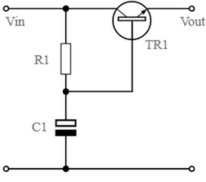
Basic Capacitance Multiplier Circuit
- The simplest emitter follower with a capacitor on the base and a feed resistor from the input to the base to switch on the transistor makes up the basic capacitance multiplier circuit. The smoothing is provided by a capacitor running from the base to ground.

- The operation of the capacitance multiplier circuit is very simple. It performs the simple emitter follower function. The capacitor provides smoothing, while the resistor R1 provides bias for the base-emitter junction. This significantly lowers the noise levels on the output or Vout.
- The capacitance on the base is effectively multiplied by the transistor’s current gain when the transistor is included in the circuit, or by.
- As a voltage regulator, the capacitance multiplier circuit is not. Since there is no voltage reference, the output voltage varies directly with the input Vin. When a load is applied, the output voltage typically drops by 2 to 3 V from Vin and by around 0.65V from the base voltage.
- Increasing the values of R1 and C1 reduces the output ripple, and this effect is amplified at low frequencies. The ripple and noise levels on the output can be lowered to very low levels. On the downside, because of their long time constants, big values of R1 and C1 cause the output to climb slowly toward the desired value after turning on.
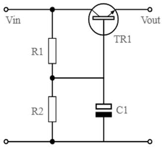
Improved Capacitance Multiplier Circuit
- Using a FET is the first step in creating a capacitance multiplier circuit (or MOSFET). BJTs are typically not utilized in capacitance multipliers because of their gain of 1. A transistor with a greater DC gain (beta value) provides a larger capacitance multiplication factor in a capacitance multiplier circuit. Be aware that a capacitance multiplier, regardless of whether it incorporates a transistor, is not a voltage regulator, even if it can undoubtedly be used in conjunction with a switching regulator or a typical linear regulator (on the input or output) (normally on the input). This circuit takes use of transistor saturation and is intrinsically nonlinear.

- The following diagram illustrates a straightforward transistor-based capacitance multiplier circuit. The two resistors in this circuit serve as a voltage divider to control the voltage applied to the transistor base and the voltage drop across the transistor. For larger output voltage, simple capacitance multiplier circuits will occasionally eliminate R2, however, this lowers the circuit’s level of noise suppression. The transistor is more easily driven into saturation when R2 is used in parallel with the capacitor because the collector-base voltage is lower. As a result, the output from the transistor will saturate at a lower level. However, this causes a greater drop in the collector-emitter voltage, which causes more power to be lost as heat.
- Here, it’s crucial to drive the transistor to saturation since doing so prevents input voltage ripple from affecting the output voltage. To make sure the transistor approaches saturation when driving the capacitance multiplier at a lower input voltage, you must apply a lower collector-base voltage (i.e., R2 > R1). If the input voltage is high enough, the output voltage can be changed by changing the values of R1 and R2.
- The capacitance C in this circuit is increased to (1 + beta)*C, where beta is the transistor gain. The capacitor C behaves as though its capacitance is (1 + beta)*C, in other words. While a single transistor has a limited gain, a Darlington pair can provide significantly greater capacitance multiplication factors.
Example Applications
- A capacitance multiplier is depicted “in context” inside the circuit of an AC to DC power supply in the following schematic.
![]()
- After the rectifier bridge, C1 serves as a storage capacitor, while C3 adds another capacitor to respond more quickly to changes in load.
