- A relay is an electrically operated switch.
- It consists of a set of input terminals for single or multiple control signals, and a set of operating contact terminals.
- The switch may have any number of contacts in multiple contact forms, such as make contacts, break contacts or combinations thereof.
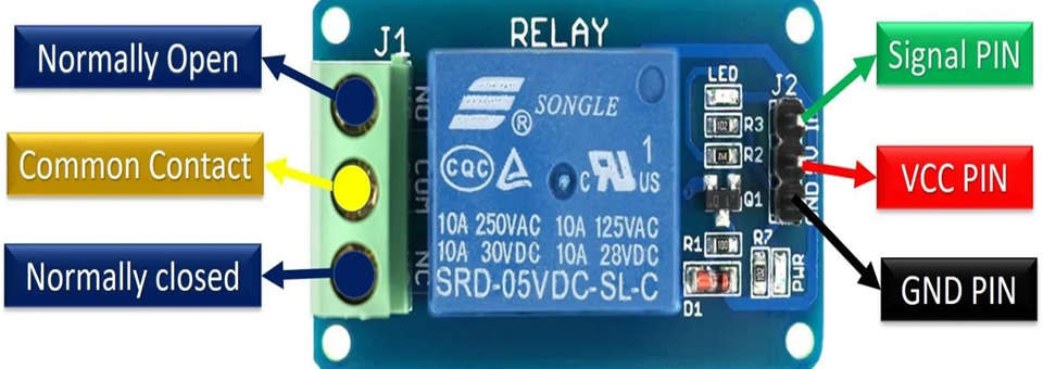
Pin Configuration

- SIGNAL PIN – It is a control pin. This signal will energize the relay coil to make contact with the common terminal with the normally open terminal. This pin can be active low or active high.
- VCC PIN – That means it requires 5V DC to operate. Hence, connect the 5v DC power supply to this pin.
- GND PIN – connected to ground.
- COMMON PIN- This terminal is connected with the load that we want to switch with the relay module.
- NC PIN – It is normally connected with the COM pin and forms a closed circuit. But this normally closed connection breaks when the relay is activated by applying an active high or active low signal.
- NO PIN – This pin is normally open unless we apply an activation signal to the signal pin of the 5V single channel relay. when the relay gets activated common pin disconnects the NC pin and connects to the NO pin.
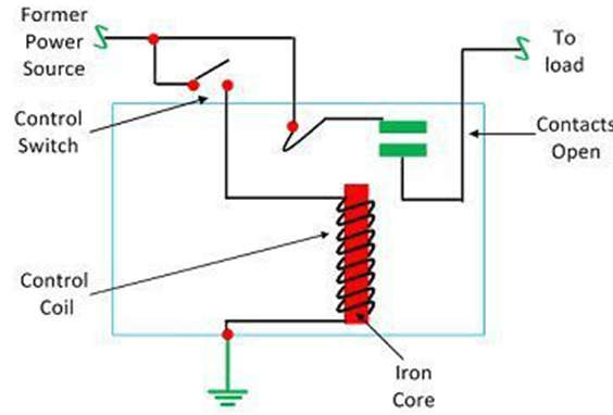
Internal circuit:

- It works on the principle of electromagnetic attraction. When the circuit of the relay senses the fault current, it energizes the electromagnetic field which produces the temporary magnetic field.
- The inner section of the relay has an iron core which is wound by a control coil. The power supply is given to the coil through the contacts of the load and the control switch. The current flows through the coil and produces the magnetic field around it.
- Due to this magnetic field, the upper arm of the magnet attracts the lower arm. Hence close the circuit, which makes the current flow through the load. If the contact is already closed, then it moves oppositely and hence opens the contacts.
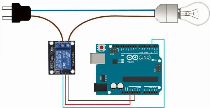
Connections of 5V relay module:

Applications of 5V Relay Module
- Mains switching
- High current switching
- Isolated power delivery
- Home automation
