- A voltage multiplier is an electrical circuit that converts alternating current (AC) power from a lower voltage to a higher DC voltage, typically through the use of a network of capacitors and diodes.
- Voltage multipliers can generate a few volts for electronic appliances all the way up to millions of volts for high-energy physics experiments and lightning safety testing. The half-wave series multiplier, also known as the Villard cascade, is the most common type of voltage multiplier.
- A voltage multiplier is a specialized rectifier circuit that produces an output that is
theoretically an integer multiple of the AC peak input, such as 2, 3, or 4. Thus, a doubler can produce 200 VDC from a 100 Vpeak AC source, and a quadruple can produce 400 VDC. In a practical circuit, any load will reduce these voltages.
Types of Voltage Multipliers
There are four types of voltage multipliers.
- Half-wave voltage doubler
- Full-wave voltage doubler
- Voltage more triple
- Voltage quadruple
1. Half-Wave Voltage Doubler
- Figure(a) below depicts the input waveform, circuit diagram, and output waveform. The forward-biased D1 diode conducts throughout the positive half cycle, while diode D2 is turned off. At this point, the capacitor (C1) is charging to Vsmax (peak 2o voltage). During the negative half cycle, the forward biased D2 diode conducts while the D1 diode is turned off. C2 will begin charging at this point.
![]()
- D2 is biased in the reverse throughout the next positive half cycle (open circuited). C2 capacitor discharges through the load at this time, resulting in a drop in voltage across this capacitor.
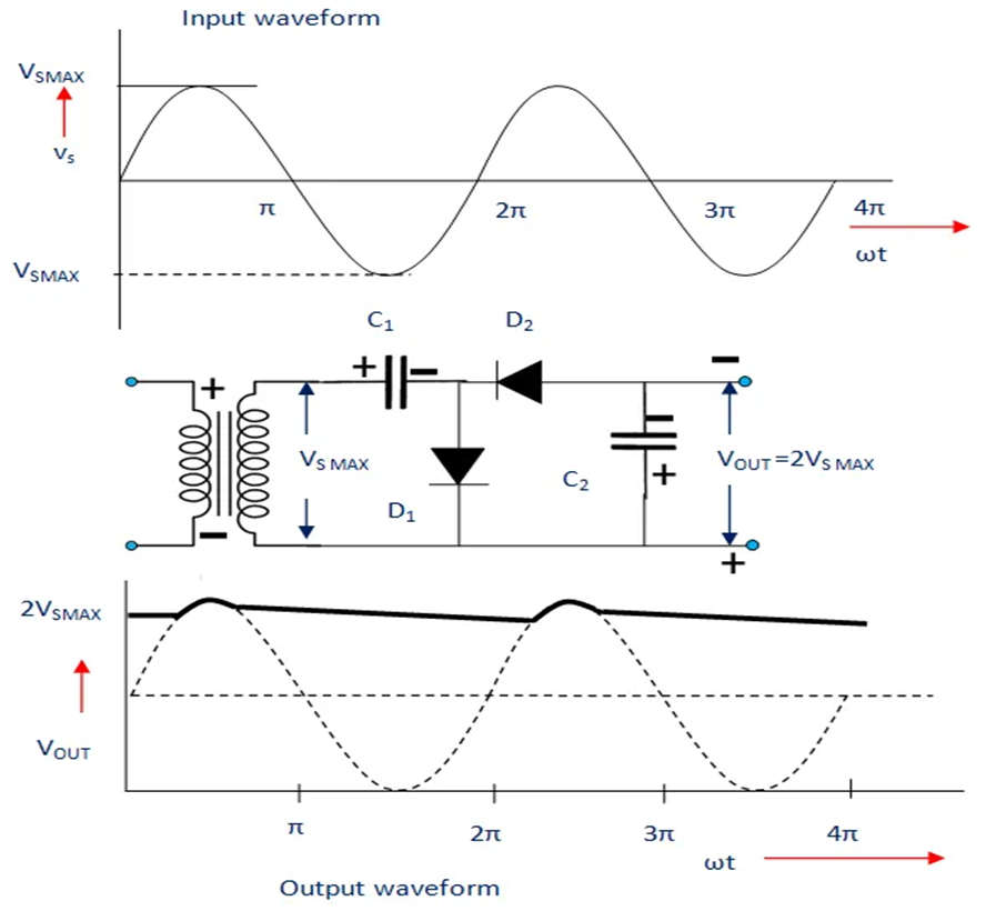
- However, if there is no load across this capacitor, both capacitors will be charged. C1 is charged to Vsmax, while C2 is charged to 2VSmax. During the negative half cycle, the C2 is charged once more (2VSmax). Across the capacitor C2 in the next half cycle, a half wave filtered by a capacitor filter is obtained. The ripple frequency is the same as the signal frequency in this case. This circuit can produce a DC output voltage of the order of 3kV.
2. Full-Wave Voltage Doubler
- A pair of series stacked half-wave rectifiers form the full-wave voltage doubler. (See diagram below.).
- Analysis of Full-Wave Voltage Doubler Operation,
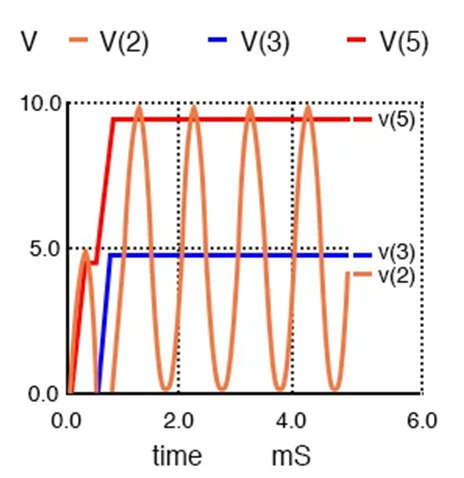
- On the negative half cycle of the input, the bottom rectifier charges C1. On the positive half cycle, the top rectifier charges C2. Each capacitor accepts a 5 V charge (4.3 V considering diode drop). The output at node 5 is the sum of C1 and C2, or 10 V. (8.6 V with diode drops).
- A full-wave voltage doubler is made up of two half-wave rectifiers with alternating polarities.
- It is worth noting that the output v(5) Figure below reaches its maximum value within one cycle of the input v(2) excursion.
- Making Full-wave Rectifiers from Half-wave Rectifiers
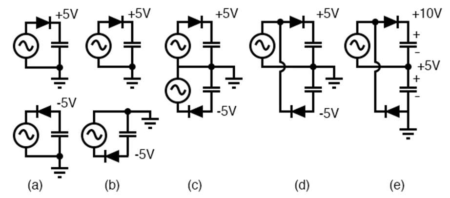
- The diagram below depicts the creation of a full-wave doubler from a pair of opposite polarity half-wave rectifiers (a). For clarity, the pair’s negative rectifier is redrawn (b). Both are combined at (c) because they share the same ground. The negative rectifier is rewired at (d) to share a single voltage source with the positive rectifier. This produces a 5 V (4.3 V with diode drop) power supply; however, 10 V can be measured between the two outputs. The ground reference point is moved to provide +10 V concerning the ground.
3. Voltage more Triple
- Adding one more diode-capacitor stage to the half-wave voltage doubler circuit yields the voltage more triple.
During the first half of the positive cycle:
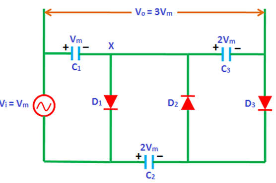
- The diode D1 is forward biased during the first positive half cycle of the input AC signal, while the diodes D2 and D3 are reverse biased. As a result, the diode D1 allows electric current to pass through it. This current flows to the capacitor C1 and charges it to the maximum value of the input voltage, Ie. VM.
In the negative half cycle:
- Diode D2 is forward-biased during the negative half cycle, while diodes D1 and D3 are reverse-biased. As a result, the diode D2 allows electric current to pass through it. This current will flow to and charge the capacitor C2. C2 is charged twice the peak voltage of the input signal (2Vm). This is due to the discharge of the charge (Vm) stored in capacitor C1 during the negative half cycle.
- As a result, the capacitor C1 voltage (Vm) and the input voltage (Vm) are added to the capacitor C2 voltage (Vm + Vm = 2Vm). As a result, the capacitor C2 charges to a voltage of 2Vm.
During the second half of the positive cycle:
- Diode D3 is forward-biased during the second positive half cycle, whereas diodes D1 and D2 are reverse-biased. Because the voltage at X is negative due to the charged voltage Vm across C1, diode D1 is reverse biased, and diode D2 is reverse biased due to its orientation. The voltage (2Vm) across capacitor C2 is thus discharged. This charge flows to capacitor C3 and charges it to the same voltage of 2Vm.
- The capacitors C1 and C3 are connected in series, and the output voltage is measured across the two capacitors. The voltage across capacitor C1 is Vm, and the voltage across capacitor C3 is 2Vm. As a result, the total output voltage equals the sum of capacitor C1 and capacitor C3 voltages, i.e. C1 + C3 = Vm + 2Vm = 3Vm.
- As a result, the total output voltage obtained by the voltage more than triple is 3Vm, which is three times the applied input voltage.
4. Voltage Quadruple
- A voltage quadruple is a stacked combination of two doublers, as illustrated in Figure. Each doubler supplies 10 V (8.6 V), for a series total of 20 V at node 2 concerning the ground.
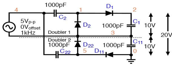
- Voltage quadruple, composed of two doublers stacked in series, with output at node 2.
- Figure below depicts the quadruple’s waveforms. There are two DC outputs: v(3), the doubler output, and v(2), the quadruple output. Some intermediate voltages at clampers show that the input sinewave (not shown), which swings by 5 V, is clamped at higher levels: v(5), v(4), and v(3) (1). Strictly speaking, v(4) is not a clamper output. It is simply the AC voltage source connected in series with the v(3) output of the doubler. v(1), on the other hand, is a clamped version of v. (4)
![]()
Applications of Voltage Multiplier
- Cathode Ray Tubes
- X-ray system, Lasers
- Ion pumps
- Electrostatic system
- Traveling wave tube
- Copy machines
- Electrostatic systems
- Photomultiplier tubes
