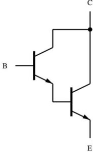
- A Darlington configuration (also known as a Darlington pair) in electronics is a circuit consisting of two bipolar transistors with the emitter of one transistor connected to the base of the other so that the current amplified by the first transistor is amplified further by the second.
- Both transistors’ collectors are linked together. This configuration has a significantly higher current gain than each transistor alone. It functions and is frequently packaged as a single transistor. Sidney Darlington invented it in 1953.
- Darlington transistor pairs are constructed from two individually connected bipolar transistors or a single device commercially manufactured in a single package with the standard: Base, Emitter, and Collector connecting leads and are available in a wide range of case styles and voltage (and current) ratings in both NPN and PNP versions.

Working and Analysis
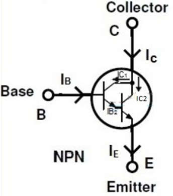
- Consider the NPN Darlington transistor configuration. A very small base current causes a large emitter current to flow, which is then applied to the next transistor’s base.
- The current gain of the second transistor amplifies the amplified current in the first transistor. As a result, the second transistor’s emitter current is very large, which is sufficient to drive large loads.

- If the first transistor’s current gain is β1 and the next transistor’s current gain is β2, the overall current gain of transistors will be the product of β1 and β2. The value for a standard transistor is 100. As a result, the total current gain is 10,000. When compared to a single transistor, this value is very high, resulting in a high load current.
- In general, the base input voltage must be greater than 0.7V to turn on the transistor. Because there are two transistors in this configuration, the base voltage must be greater than 1.4V.
- According to the diagram, the current gain of the first transistor is,β1= IC1/IB1,therefore IC1 = β1 IB1
- Similarly, the next transistor’s current gain,β2= IC2/IB2, then IC2= β2 IB2
The total current at the collector is IC= IC1+IC2IC = β1 IB1 + β2 IB2 - However, the second transistor’s base current,IB2 = IB + IC1IB2 = β1 IB + IBIB2 = IB(1 + β1)
- In the preceding equation, substitute IC = β1IB + β2IB (1 + β1)
IC = IB (β1 + β2 + β1β2) - Individual gains are ignored in the above relationship, and the total equation is approximated as,IC= IB (β1β2)
- That is the total gain,β = (β1β2)
And also VBE = VBE1 + VBE2.
Applications of Transistor Darlington Pair
- As previously demonstrated, the Darlington pair amplifier circuit can provide a significant current gain.
- It has a wide range of use as a current Amplifier.
- Darlington pair circuit can also be used in Voltage regulators.
- As power amplifiers in electronic devices like TV, computers, etc.
- To detect current in the skin.
- It is used as a switch in a water level indicator.
- To construct a touch-sensitive button, connect it to a metal piece.
Advantages of Transistor Darlington Pair
- In comparison to a single transistor, it has a very high current gain.
- It has an extremely high input impedance.
- It has few components and can thus be used for simple circuit designs.
- It can amplify signals to a greater extent.
- It enables designers to drive higher-power applications with a few milliamperes of current.
- It is extremely current sensitive.
Disadvantages of Transistor Darlington Pair
- When the Darlington pair is in saturation (i.e. fully ON), there is a voltage drop across the base (“B”) and emitter (“E”) terminals.
- The switching speed is reduced.
- The available bandwidth is limited.
- This configuration causes a phase shift in the negative feedback circuit at certain frequencies.
- Because of the high saturation voltage, it has a high power dissipation.
- The next transistor amplifies the leakage current of the first transistor. As a result, the overall leakage current of the Darlington pair is greater.
