- A current mirror is a circuit that copies a current through one active device by controlling the current in another active device in the circuit, maintaining the output current constant regardless of loading. The “copied” current can and sometimes is a varying signal current. An ideal current mirror is simply an ideal inverting current amplifier that also reverses the current direction. It could also be a current-controlled current source (CCCS).
- We know that the collector current in an active transistor is equal to the base current multiplied by the ratio. We also know that the ratio of collector current to emitter current is known as. Because collector current equals base current multiplied by and emitter current equals the sum of base and collector currents, should be derivable mathematically. If you do the math, you’ll discover that = /(+1) for any transistor.

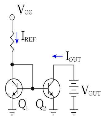
- A current mirror made of NPN bipolar transistors that use a resistor to set the reference current IREF; VCC is a positive voltage shown in the above figure.
- We’ve all seen how maintaining a constant base current through an active transistor result in collector current regulation based on the ratio. The ratio works similarly: if the emitter current is held constant, the collector current will remain stable and regulated as long as the transistor has enough collector-to-emitter voltage drop to keep it active. As a result, if we can maintain a constant emitter current via a transistor, the transistor will work to maintain a constant collector current.
- Remember that, like a diode, the base-emitter junction of a BJT is nothing more than a PN junction, and that the “diode equation” specifies how much current will flow through a PN junction given forward voltage drop and junction temperature.
Diode Equation Formula
![]()
Current Mirror’s Limitations
- The current mirror circuit described above, which uses two transistors, is frequently adequate for most applications. However, it includes some restrictions below several conditions, such as the following.
- The ideal circuit and the real circuit are opposed. There is no such thing as perfect or ideal in the real world. However, to understand the limitations of current mirror circuits in real-world applications, one must first understand the voltage and current sources, as well as their ideal and actual behaviors.
- A voltage source is a device that can supply a fixed and stable voltage to a load. In ideal terms, the voltage source will always provide a constant voltage that is independent of the load current. As a result, we can connect any load resistance across the ideal voltage source and always get a stable and fixed voltage. In a real-world voltage source, this is not the case. Voltage sources, such as batteries and power supplies, cannot provide unlimited or infinite currents to loads in the real world.
- The current source, like the ideal voltage source, can deliver or accept currents regardless of the terminal voltage. In practice, however, voltage has an impact on the constant current delivery process.
- The voltage and current sources are ideal in current mirror circuits. However, in practice, there are noises, tolerances, and ripples, so the output voltage varies. This all has an impact on the current mirror output.
- Not only that, but in ideal current mirror circuits, the AC impedance is assumed to be infinite, but this is not the case in practice. In the real world, the current mirror circuit has finite impedance, which affects the current delivery process. Furthermore, the circuit implementation generates parasitic capacitance, which limits the frequency.
Characteristic and Dependency of Current Mirror Circuit
- The primary concern in characterizing a current mirror circuit is the number of primary and secondary dependencies.
Three specifications can be used to characterize a proper current mirror circuit.
Ratio of Current Transfer
- A current mirror circuit mirrors or copies the input current of one active device to the output of another active device. An ideal current mirror circuit is an ideal current amplifier with an inverting configuration that can reverse the current direction. As a result, the current transfer ratio is a critical parameter for an ideal current amplifier.
AC Output Resistance
- The ohms law states that resistance has a voltage-current relationship. Thus, AC output resistance plays a major role in the stability of output current concerning voltage changes.
Voltage Drop
- The output of a properly functioning mirror circuit has a low voltage drop. Compliance range refers to the voltage range in which a Current Mirror Circuit can operate, and compliance voltage refers to the minimum to maximum supported voltage in this compliance range. Because a minimum voltage is required to keep the transistor active, the minimum voltage is determined by the transistor specifications.
Wilson’s Current Mirror Circuit
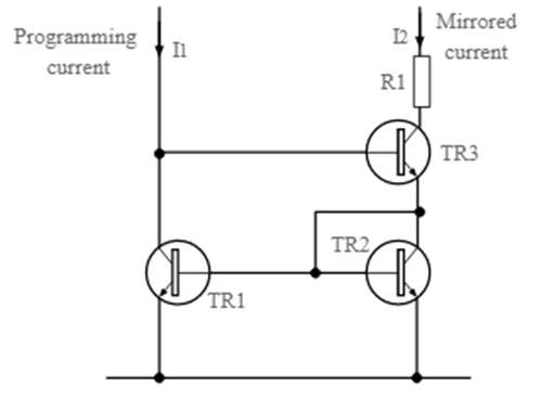
- The Wilson mirror or Wilson current mirror is another variation of the basic current mirror circuit.
- A third transistor is added to the circuit. This transistor, labeled TR3 in the diagram, maintains TR1’s collector at a voltage equivalent to two diode drops below the rail voltage Vcc.

- This cancels out the previous effect. Also, without the short circuit collector base connection, the transistor becomes the programming terminal.
- Current mirror circuits are very useful, especially within integrated circuits. The components are simple to incorporate into the design and are inexpensive. As a result, they enable balanced currents to be supplied to circuits such as differential pairs and the like, further improving their operation. Current mirrors are not widely used outside of IC technology due to the additional number of components required, but the principles are the same in both discrete and IC forms.
