


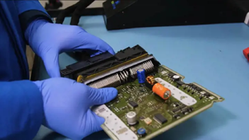
What is an ECU?
An essential part of contemporary cars is the engine control unit (ECU), which aids in controlling and maintaining a number of engine performance parameters.

Preparation for Testing ECU
Tools and Equipment Needed:
OBD-II Scanner

Oscilloscope
ECU Testing Harness
Diagnostic Software
Screwdrivers, Pliers, and Socket Set
Safety Glasses and Gloves
Safety Precautions:
Disconnect Battery
Wait for Cooling
Handle Electronics Carefully
Follow Manufacturer Instructions
Work in a Well-Ventilated Area
Use Proper Tools
Setting Up Your Multimeter
Choosing the Right Settings:
- Select the Function: Determine what you are measuring (voltage, resistance, or continuity).
Voltage Measurement:
– Depending on the system being tested, choose an AC (alternating current) or DC (direct current) voltage. For automotive applications, you’ll typically use DC.
– Select the appropriate voltage range. Start with a higher range and switch to lower ranges for more precise measurements if needed.
- Resistance Measurement:
– Select the resistance (Ω) function.
– Choose an appropriate range based on the expected resistance. Start with the highest range and decrease as necessary.
- Continuity Test:
– Some multimeters have a specific continuity setting (often denoted by a diode symbol or sound wave symbol).
– This setting checks if there is a complete path between two points, indicating continuity (low resistance).
Connecting the Multimeter Correctly:
- Turn Off Power: Ensure the vehicle’s ignition is off before connecting the multimeter.
- Voltage Measurement:
– Black Lead (COM): Connect to the common (COM) terminal on the multimeter.
– Red Lead (VΩmA): Connect to the terminal labeled for voltage (V) and resistance (Ω) measurements.
– Connect the black lead to a ground point or battery negative terminal.
– Connect the red lead to the point where you want to measure voltage (e.g., battery positive terminal, sensor output).
- Resistance Measurement:
– Black Lead (COM): Same as above, connect to the common (COM) terminal.
– Red Lead (VΩmA): Also same as above, connect to the terminal labeled for resistance (Ω) measurements.
– Connect the leads across the component or circuit you want to measure resistance across.
- Continuity Test:
– Follow the same lead connections as for resistance measurement.
– To test for continuity, touch the probe to the desired location (such as a fuse, switch, or cable).
Testing Procedures
Testing procedures for an Engine Control Unit (ECU) involve verifying various electrical signals to ensure proper operation. Here’s how you can check power supply voltages, test sensor inputs and outputs, and verify communication signals:
1. Checking Power Supply Voltages:
– Dissociate the battery and turn off the launch- up for safety’s sake.
– Locate the ECU: Find the ECU in the machine cube or beneath the dashboard of the auto.
– To determine the position and function of each pin in the schematic ECU pin illustration, consult the vehicle service primer.
– Adjust the range of your multimeter to suit the DC voltage you want to measure (typically 20V DC).
– Connect the multimeter:
– Black lead (COM) to a good ground point on the vehicle (e.g., battery negative terminal or chassis ground).
– Red lead (VΩmA) to each ECU power supply pin as specified in the manual.
– Check voltages: With the ignition on (engine off), measure voltages at each power supply pin to ensure they match the specified values in the manual. Typical voltages include +12V, +5V, and sometimes +3.3V depending on the system.
2. Testing Sensor Inputs and Outputs:
– Identify sensors: Find the sensors that are connected to the ECU, such as the oxygen (O2), TPS (throttle position sensor), and MAF (bulk air flow).
– Depending on the kind of sensor, adjust the multimeter to detect voltage or resistance. (Active sensor voltage) Resistance in passive sensors (temperature sensors, for example).
– Cut the sensor connector’s connection to the ECU.
– Connect the multimeter probes to the sensor connector pins:
– For voltage sensors: Join the black wire to ground and the red wire to the signal output wire. Inspect the voltage indicated (e.g., 0-5 V, depending on the sensor) or 0-1 V.
– For resistance sensors: Check the resistance value listed in the handbook and measure the resistance between the sensor terminals.
– Operate the sensor: Depending on the type of sensor, replicate different processes (e.g. throttle movement for TPS). and track any related changes in resistance or voltage.
3. Verifying Communication Signals:
– Use an OBD-II scanner: Attach the scanner to a standard OBD- II harborage beneath the dashboard of the vehicle.
– Turn on the scanner and attach it to the ECU of the auto.
– Access live data: Check parameters using the scanner, such as engine speed. Temperature of the coolant and sensor readings.
– Check for DTCs: Extract diagnostic trouble codes (DTCs) from the memory of the ECU. Keep track of the codes linked to miscommunications.
– Inspect wiring and connectors: Visually check the wiring harness and connectors for corrosion or other issues that could impair communication.
Interpreting Results
Normal Readings:
– Power Supply Voltages: Voltage readings should match specifications provided in the vehicle’s service manual.
– Sensor Inputs: Voltage signals should correspond to expected values based on sensor operation and vehicle conditions.
– Communication Signals: Successful communication with the ECU, no error codes (DTCs), and consistent data transmission.
Abnormal Readings:
– Power Supply Voltages: A departure from the intended value (such as an excessively high or low voltage) suggests that there may be an issue with the fuses, wires, or ECU itself.
– Sensor Inputs: A sensor malfunction could be indicated by an inaccurate voltage or resistance value. Issues with sensor calibration or wiring defects.
– Communication Signals: Intermittent communication, communication issues with the ECU, or trouble codes (DTCs) associated with communication errors.