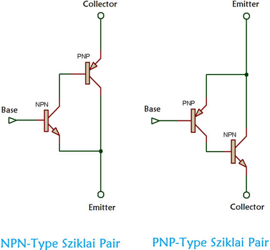
- The Sziklai pair, also known as a complementary feedback pair in electronics, is a configuration of two bipolar transistors similar to a Darlington pair. Because the Sziklai pair, unlike the Darlington arrangement, has one NPN and one PNP transistor, it is also known as the “complementary Darlington.”
- Darlington and Sziklai both have two configurations. Sziklai’s configurations, on the other hand, have an equal base-emitter voltage drop to a normal transistor. Darlington’s base-emitter voltage drop is twice as large. The sziklai pair is commonly used in push-pull and class AB audio amplifier output stages.

- Sziklai pair have two configurations, as shown in the image above. The first is an NPN sziklai pair, in which transistor Q1 is NPN and transistor Q2 is PNP. The second is a PNP type sziklai pair, with transistor Q1 being PNP and transistor Q2 being NPN.
- The gains of the Sziklai and Darlington are roughly equivalent.
- Sziklai Pair Gain: β = βQ1 x βQ2 + βQ1
Darlington Pair Gain: βQ1 x βQ2 + βQ1 + βQ2 - In practical, the total gain for both pairs is roughly equal to:
β = βQ1 x βQ2
Features of Sziklai Pair
Although the Darlington is widely used, the Sziklai pair has several advantages and can be used effectively in a variety of applications. It has the following features.
- There is only one base-emitter drop between the compound transistor’s overall base and emitter.
- A Darlington has a slightly lower gain.
- Saturation voltage is higher than in a Darlington.
- Can be used to generate a pseudo-complementary output with a Darlington – a true complementary pair would use both circuit configurations. This design employs three NPN transistors and one PNP transistor. It has several advantages, including.
- The performance of the lower “pull” pair, which uses a single NPN transistor, is more similar to that of the upper “push” pair, which uses two NPN transistors (PNP transistors have lower carrier mobility). In a true complementary pair, the lower pair would be all NPN and the upper pair would be all PNP.
- Previously, silicon PNP transistors were more expensive than their NPN counterparts due to processing techniques and volume usage, particularly for power transistor versions.
- Because many PNP transistors with nearly equivalent performance to their NPN counterparts are now available, the benefits of using the Sziklai / compound pair are diminishing.
- The Sziklai pair is known to have higher linearity than the Darlington pair, which can be advantageous in audio applications.
- The Sziklai compound pair has numerous applications in electronics. The most common applications are probably in audio output stages, where it can be used as one half of a push-pull amplifier, with the other half being a Darlington. As a result, the Sziklai pair allows the output to operate with complementary symmetry.
- The Sziklai pair is also used in a variety of digital circuits. Again, it allows outputs to operate in complementary symmetry, and the fact that it only requires a single diode voltage drop across the input rather than two for a Darlington makes it appealing in many applications.
Which is Better Sziklai Pair Or Darlington Pair?
- Because Sziklai Pair addresses the issues with Darlington Pair, it is generally preferable to use Sziklai Pair, but this depends on the application. Here are a few benefits of the Sziklai pair.
- For better linear operations, the Sziklai pair has a lower quiescent current.
- The thermal stability of the Sziklai pair outperforms that of the Darlington pair.
- It responds faster than the Darlington pair.
- The sziklai pair has the same turn-on voltage as a normal transistor, whereas Darlington requires twice the input voltage.
- However, there are a few drawbacks, such as the sziklai pair’s lower gain than the Darlington pair.
Applications of Sziklai Pair
- These are some examples of Sziklai pair applications.
- In some applications, a sziklai pair can function as a single transistor of the same type as Q1 with a high current gain.
- The emitter of transistor Q2 serves as a collector. As a result, C represents the emitter of transistor Q2.
- Q2’s emitter performs the function of a collector. As a result, the Q2 emitter is labeled “C” in the figure to the right.
- In normal applications, the collector of transistor Q2 serves as the emitter and is denoted as E.
