What is The RC Integrator?
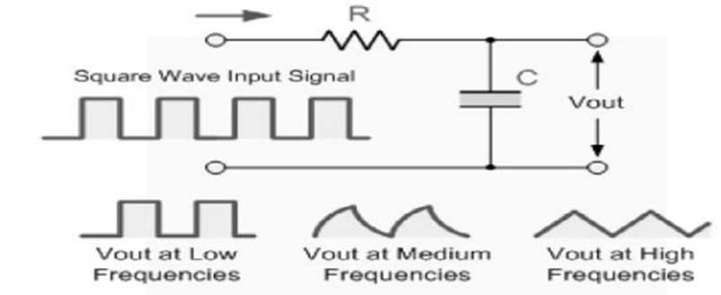
- The Integrator is essentially a time domain low pass filter circuit that converts a square wave “step” response input signal into a triangular-shaped waveform output as the capacitor charges and discharges.
- A triangular waveform is made up of positive and negative ramps that alternate but are equal. As shown below, if the RC time constant is longer than the period of the input waveform, the resulting output waveform will be triangular, and the higher the input frequency, the lower the output amplitude in comparison to the input.

- As a result, this circuit is ideal for converting one type of electronic signal to another for use in wave-generating or wave-shaping circuits.
RC Integrator
- An integrating circuit is one in which the output voltage is proportional to the integral of the input voltage. Resistors and capacitors are two of the most commonly used circuit elements in electronics. A capacitor is a type of circuit element that stores charge between two conductors, thereby storing electrical energy in the form of a field E. (R, t). In contrast, an inductor stores energy in the form of a magnetic field B. (R, t). The process of storing energy in the capacitor is known as “charging,” and it involves the accumulation of an equal number of charges of opposite signs on each conductor. A capacitor’s ability to hold a charge, which is proportional to the applied voltage, defines it.
Q = C V - The capacitance is defined as the proportionality constant C. A simple capacitor model consists of two parallel conducting plates separated by air or a dielectric of cross-sectional area A. Because the presence of the dielectric prevents the flow of DC, a capacitor acts as an open circuit in the presence of a DC. If, on the other hand, the voltage across the capacitor terminals varies over time, the charge accumulated on the capacitor plates is given by:q (t) = C V (t)
- Although no current can flow through a capacitor with a constant voltage across it, a time-varying voltage causes the charge to vary over time. As a result, if the charge changes over time, the current in the circuit is given by:
![]()
- Electrical signal shapes must frequently be modified to be in a suitable form for circuit operation. The simple RC circuit is frequently used in the formation of suitable waveforms.
![]()
- Because the reactance of the capacitor decreases with increasing frequency, the circuit readily passes low frequencies but attenuates high frequencies. At very high frequencies, the capacitor acts as a virtual short circuit, resulting in zero output. This circuit also functions as an integrating circuit. The RC value for the integrating circuit must be much greater than the period of the input wave (RC >> T).
- Let Vi denote the alternating input voltage and I denote the resulting current. When Kirchhoff’s Voltage Law is applied to an RC low pass circuit,
![]()
- By multiplying everything by C, we get
![]()
- as RC >> T, the term, ” ∫ot I dt ” may be neglectedC Vi = iRC
- We get by integrating concerning T on both sides
![]()
![]()
RC Integrator as a Sine Wave Generator
- We saw earlier that an RC integrator circuit can perform integration by applying a pulse input, resulting in a ramp-up and ramp-down triangular wave output due to the capacitor’s charging and discharging characteristics. But what if we reversed the process and applied a triangular waveform to the input? Would we get a pulse or a square wave?
- When a pulse-shaped input signal is used in an RC integrator circuit, the output is a triangular wave. However, when we apply a triangular wave, the output becomes a sine wave due to the ramp signal’s integration over time.
- There are numerous methods for producing a sinusoidal waveform, but one simple and inexpensive method is to use a pair of passive RC integrator circuits connected in series as shown.
![]()
- The original pulse-shaped input is converted by the first RC integrator into a ramp-up and ramp-down triangular waveform, which becomes the input of the second RC integrator. This second RC integrator circuit effectively performs a double integration on the original input signal, rounding off the points of the triangular waveform and converting it to a sine wave, with the RC time constant affecting the degree of integration.
- Because ramp integration yields a sine function (basically a rounded-off triangular waveform), its periodic frequency in Hertz is equal to the original pulse’s period T. Also, if we reverse this signal and the input signal is a sine wave, the circuit does not act as an integrator, but as a simple low pass filter (LPF), with the sine wave changing only in amplitude because it is a pure waveform.
Applications of RC Integrator
- Analog computers use Integrator Circuits.
- These are also employed in the Analog to Digital Converter Circuit.
- These are also used for analog signal conversion, such as modulations.
- Wave Shaping Circuits also make use of these.
