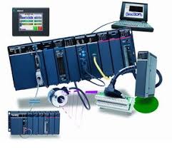
- PLC stands for “programmable logic circuit”
- It is general-purpose computer modified specifically to perform control tasks.
- It is used for industrial automation.
- These controllers can automate a specific process, machine function, or even an entire production line.
- PLC is developed as an electronic replacement for hard-wired relay logic system for machine control.
- It is a microprocessor based control system.
- They are designed for industrial use to control many automated processes in the industry.
- PLCs were invented by dick Morley in 1964.
- The term PLC has revolutionized the industrial and manufacturing sectors. There is a wide range of PLC functions like timing, counting, calculating, comparing, and processing various analog signals.
Block diagram of PLC
- Programming Logic Controller is basically a multiple inputs multiple output system so these are the input of the PLC system and these are the output or load devices of the system. In PLC input is given in any form any physical form, analog form, or digital form. The physical form just like we give input in the form of temperature, pressure, humidity, electrical signal, digital signal, limit switches, and at the output side PLC operate the electric motor, pneumatic motor, hydraulic cylinder, lamps, magnetic relay so these are the input and these are the output. This is called the input module this is output module PLC having a Central Processing Unit and memory and power supply and to program this PLC we use an external Programmable device that is a laptop or any desktop this is connected with the help of an Ethernet cable.
- How many numbers of inputs and output depends upon the size of the PLC. Basically PLC is available in three sizes small medium and large which is depends on how many tasks performed by the PLC. Now if we compare this block diagram with the actual PLC so this is a power supply unit of PLC. This is the CPU of the PLC it means a central Processing Unit of PLC. Here the CPU is connected with a Programmable device with the help of an Ethernet cable, now these are the input-output section here we connect input and output so this is digital input here we get digital output analog input, analog output, DC input, and DC output. Now, this is called a wrap. now this passage here we see this is called rag and this rack is basically used to extend the input-output capability of the PLC system, here we put input or output cards so this is a basic comparison between the actual PLC and the block diagram of PLC.
- PLCs are used to automate industrial processes such as a manufacturing plant’s assembly line, an ore processing plant, or a wastewater treatment plant.
- A PLC is a computer specially designed to operate reliably under harsh industrial environments such as extreme temperature, wet environment, dry condition, and dusty environment.
