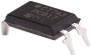
- A type of semiconductor device known as an optocoupler, also known as an optoisolator, photo-coupler, or optical isolator, enables the transmission of electrical signals between two separated circuits by light. A photosensitive device and an LED are two parts of this component. Optoisolator integrated circuits (ICs) come in a variety of forms, including the PC817 IC, MOC3021 IC, MOC363 IC, MCT2E IC, and PC817 optocoupler.
What is a PC817 Optocoupler?
- Optocoupler PC817 IC has an IR diode and a phototransistor. Filters are essential in many circuits for removing noise. The resistor and value capacitor frequently depend on the incoming signal even though the circuit with the resistor and capacitor always removes the noise from the signal.

- This circuit is only acceptable in situations where the incoming signal has some data, but we must combine IR Tx and Rx when we need to transfer a signal from one element of the circuit to another element of the circuit even when the signal contains noise.
- In the PC817 optocoupler circuit, the IR receives the noisy signal from one component and sends it to another using the IR signal to enable the circuit to function as intended. An LED and a phototransistor are included in the PC817 IC and are optically coupled to one another. Without a physical connection, the signal can be carried optically between the i/p and o/p sides.
- It can be linked directly to any microcontroller or other DC device with less voltage. The input voltages will have a comparable impact on each face of this IC; it will merely send the signal in the receiver’s direction. The receiver will then produce the logic signal after that. Due to its small size and versatile control function, this IC has many applications.
PC817 Optocoupler Pin Configuration
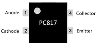
The pin configuration of PC817 Optocoupler is shown below, This IC includes 4 pins 2 input pins, and 2 output pins where each pin and its functionality is discussed below.

- Pin1 (Anode): In the optocoupler IC, this is an Anode pin of infrared LED (Tx). This pin provides a logical input signal toward the internal IR.
- Pin2 (Cathode): In this IC, this is the cathode pin of the infrared LED (Tx). It will provide the infrared to create the common GND through the circuit & power supply.
- Pin3 (Collector): This is an o/p pin of the IR Tx in the optocoupler and it provides the logical o/p through getting the infrared signal.
- Pin4 (Emitter): This is a GND pin for IR Rx in the IC & it is used to build the common GND through the circuit & power supply.
- An alternative PC817 ICs are 6N136 IC, MOC3041 IC, MOC3021 IC, 6N137 IC & 4N25IC. Equivalent PC817 ICs are PC817A, PC817C, PC817B & PC817D.
Features & Specifications of PC817 Optocoupler
The specifications of the PC817 Optocoupler include the following.
- Forward Voltage of Input Diode is 1.25V.
- At the collector terminal, the maximum current ratio is 50mA.
- The maximum Voltage of the Collector-Emitter is 80V (max).
- At the Collector & Emitter Terminals, the ratio of maximum voltage is 80V.
- Maximum Collector Current is 50mA.
- Rise Time is18us.
- Fall Time is 18us.
- The cut-off frequency is 80 kHz.
- The max operating temperature ranges from -30 to 100 degrees.
- Power Dissipation is 200mW.
- The internal resistance is 100 ohms.
- While doing soldering, the optocoupler’s temperature range is 260 degrees. Once the temperature increases then the IC will be damaged.
The features of the PC817 IC Optocoupler include the following.
- This IC includes 4-pins and is available in two packages SMT and DIP.
- This IC includes internal protection for both input & output from electrical isolation and it protects up to 5KV.
- This IC is used with an additional resistor through high voltage devices to function through fewer voltage devices.
- This IC can function through any type of device including internal interfaces such as Microcontrollers, TTL devices & also with HIGH DC voltage through some inside resistors.
- PC817 Optocoupler comes with inside safety from reverse current, because of the flow of current in one way; this IC defends the infrared from any current.
Circuit Diagram of PC817 IC Optocoupler
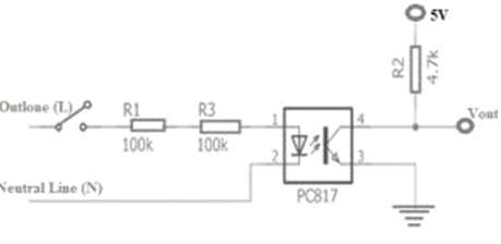
- The PC817 IC Optocoupler’s circuit schematic is displayed below. An integral part of this circuit is an IC like PC817, which is utilized to switch the DC circuit.
- The optocoupler circuit described above uses a photo-transistor and functions as a standard transistor switch. An inexpensive phototransistor with an optocoupler base is used in this design. Through the switch “S1,” an IR LED can be controlled.

- Once the switch is engaged, the 10K resistor and the 9V battery work together to direct electricity toward the LED. The resistor “R1” allows you to alter the LED’s brightness. If we change the resistance value to be lower, the transistor gain will also be higher since LED intensity will be higher.
- The IR LED can be used to control the photo-transistor on the other side of the circuit. When the LED emits IR light, the phototransistor will make contact, the output voltage will be zero, and the load that is connected beyond it will be disconnected.
- It is crucial to keep in mind that the transistor’s collector current is 50mA, as stated in the PC817 IC datasheet. The “R2” resistor, which is utilized here as a pull-up resistor, produces an output voltage of about 5V. The optocoupler, which is based on a phototransistor, is utilized in this circuit design to detect pulses that a microcontroller would otherwise interrupt.
- The PC817 optocoupler operates quite simply, although different devices have different requirements when using it. The optocoupler requires a current-limiting resistor on the input side, but we must fix the logic output pin through the power pin at the output. The generation of the infrared signal causes a shift in the current flow, which causes the logic condition to change from one to zero.
How to use it safely in a Circuit for a Long Time?
- It is advised to always keep below the absolute highest ratings when using a PC817 IC optocoupler in your circuit in a very secure manner. The internal infrared LED can be obtained by employing a current limiting resistor at pin-1, which denotes the anode or cathode pin of the IR LED. The load should not be driven above 50mA and like a normal LED.
- The device shouldn’t be used in temperatures below -30 degrees Celsius or above 100 degrees Celsius. Always keep items in storage above -55 degrees and below 125 degrees centigrade.
Applications of PC817 Optocoupler
The applications of PC817 Optocoupler include the following.
- In Isolation Circuits.
- Switching Circuits with Microcontroller I/O.
- Isolation of Signal.
- Circuits of Noise Coupling.
- AC/DC Power control.
- It is Reliable to utilize because of its functionality.
- For Transmission of Signal.
- Noise Coupling Circuits.
- Uses as Switching because of the noise factor neglect.
- Opto-coupler is used in a home appliance to regulate AC loads by giving the pulse of change within the frequency that provides the capability to manage the AC load at a fixed range.
