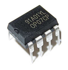
- The OP07 is a precision operational amplifier integrated circuit (IC) that contains a single operational amplifier inside a chip. The slew rate of the OP07 operational amplifier is 0.3-V/s. It has a wide input voltage range and operates with low noise. It has internal frequency compensation and offset nulling capabilities.
- Trimming at the wafer stage results in a very low input offset voltage (75 V maximum for OP07E). These low offset voltages eliminate the need for external nulling in most cases. The OP07 also has a low input bias current (for the OP07E, 4 nA) and a high open-loop gain (200 V/mV). The OP07’s low offset and high open-loop gain make it ideal for high-gain instrumentation applications.

- The noninverting circuit configuration benefits from a wide input voltage range of 13 V minimum, a high CMRR of 106 dB (OP07E), and a high input impedance. Even at high closed-loop gains, excellent linearity and gain accuracy can be maintained. The offsets and gain are extremely stable with time or temperature variations. The OP07’s accuracy and stability, even at high gain, combined with its lack of external nulling, have made it an industry standard for instrumentation applications.
What is an Operational Amplifier?
- Operational amplifiers are linear devices with all of the properties required for nearly ideal DC amplification and are thus widely used in signal conditioning, filtering, and mathematical operations such as add, subtract, integration, and differentiation.
- A differential-input stage with a high input impedance, an intermediate-gain stage, and a push-pull output stage with a low output impedance comprise an operational amplifier or op-amp.
- An operational amplifier is a three-terminal device with two high impedance inputs. The Inverting Input (-) is one of the inputs. The non-inverting input is denoted by a positive or “plus” sign (+).
- A third terminal represents the operational amplifier’s output port, which can both sink and source voltage or current. In a linear operational amplifier, the output signal is the amplification factor, known as the amplifier’s gain (A), multiplied by the value of the input signal.
Pin Configurations
The Pin diagram of OP07 Operational Amplifier IC is Given below.
| Pin Number | Pin Name | Description |
|---|---|---|
| 1,8 | VOS Trim | Used to set offset voltage if required |
| 2 | Inverting Input(-IN) | The Inverting pin of the Op-Amp |
| 3 | Non-Inverting Input (+IN) | The Non-Inverting Pin of the Op-Amp |
| 4 | V- | Connected to negative rail or ground |
| 5 | NC | Not Connected |
| 6 | Output | The output pin of the Op-Amp |
| 7 | V+ | Connected to the positive rail of supply voltage |
Features of OP07 Operational Amplifier
- Input offset voltage is extremely low. OP07E has a maximum input offset voltage of 75V.
- The input voltage range is 14 V.
- The supply voltage ranges from 3 V to 18 V.
- The CMRR is high. It is 106 dB for OP07E.
- It has a high input impedance and operates quietly.
Applications of OP07 Operational Amplifier
- Wireless base station and optical networks.
- Strain bridges.
- Instrumentation.
- Shunt current measurements.
- Resistor thermal detectors (RTDs).
- Sensors and controls.
- Thermocouples.
- Precision filters.