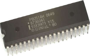
- Intel created the 8051 microcontrollers in 1981. It is a microcontroller with 8 bits. It has 40 DIP (dual inline package) pins, 128 bytes of RAM, 2 16-bit timers, and 4 KB of ROM storage. It has four parallel 8-bit ports that can be programmed and addressed following the needs. The microcontroller includes an on-chip crystal oscillator with a crystal frequency of 12 MHz.

- Because it is an 8-bit microcontroller, the data bus has 8 bits. It can therefore process 8 bits at once. A wide range of embedded systems, including robots, remote controls, the automobile sector, telecom applications, and power tools, among others, employ it.
The Architecture of Microcontroller 8051
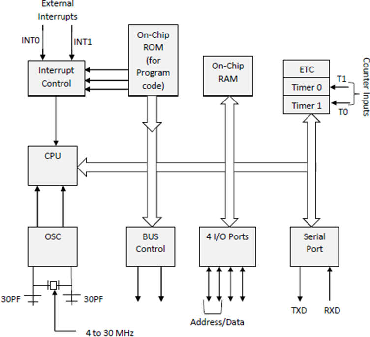
- It is based on CISC Instruction set Architecture. The system bus links all the peripherals to the CPU in the diagram that follows. An 8-bit data bus, a 16-bit address bus, and bus control signals make up the system bus. The system bus connects the CPU and every other component, including program memory, ports, data memory, serial interface, interrupt control, and timers.
Central Processing Unit (CPU):
- serve as the brains of all processing devices. It coordinates and controls all actions performed by the microcontroller. The operation of the CPU cannot be controlled by the user. It interprets the ROM-stored program, executes it from storage, and then carries out the intended task. The various register types that the 8051 microcontroller has available are managed by the CPU.

Interrupts:
- An interrupt is a subroutine call that the microcontroller issues when another program with a high priority requests access to the system buses. This causes the currently executing program to experience n interrupts. Interrupts offer a way to delay or postpone the ongoing operation while carrying out a subroutine task before restarting the main program.
Interrupt Types in an 8051 Microcontroller:
Let’s look at the five interrupt sources in the 8051 microcontrollers.
-
- Timer 0 overflow interrupt – TF0
- Timer 1 overflow interrupt – TF1
- External hardware interrupt – INT0
- External hardware interrupt – INT1
- Serial communication interrupt – RI/TI
Memory:
- A program was necessary for the microcontroller. The microcontroller is directed to carry out the specified tasks using this software. The microcontroller’s installed program needed some on-chip memory to store the program.
- Memory was also needed by the microcontroller for temporary data and operand storage. The microcontroller 8051 has a code or program memory of 4 KB, or 4 KB of ROM, and 128 bytes of RAM for data storage.
BUS:
- Essentially Bus is a group of wires that serves as a data transfer medium or communication route. These buses are made up of the microcontroller’s 8, 16, or more wires. Therefore, these can simultaneously carry 8 and 16 bits. Hire the two bus kinds that are displayed below.
- Data Bus: The data bus on the microcontroller 8051 has 8 bits, which are utilized to transport data for specific applications.
- Address Bus: The 16-bit address bus on the microcontroller 8051 is used to transport data. It is used to transmit the address from the microcontroller’s CPU to its memory and to address specific regions in memory. There are four addressing modes available.
- Immediate addressing modes.
- Bank address (or) Register addressing mode.
- Direct Addressing mode.
- Register indirect addressing mode.
Oscillator:
- Since clock pulses are necessary for the operation of microcontroller applications, we can assume that the microcontroller is a device. The microcontroller 8051 features an on-chip oscillator that serves as the Central Processing Unit of the microcontroller’s clock source for this reason. The oscillator’s output pulses are steady. Therefore, it allows the 8051 Microcontroller’s many components to operate in unison.
Input/Output Port:
- Embedded systems typically use microcontrollers to operate the machinery inside the microcontroller. Therefore, we need I/O interfacing ports in the microcontroller interface to link it to other machines, devices, or peripherals. The microcontroller 8051 features four input and output ports that can be used for this purpose.
Timers/Counters:
- There are two 16-bit timers and counters on the 8051 microcontrollers. Once more separated into an 8-bit register are these counters. The use of timers allows for the measuring of intervals and the determination of pulse width.
Pin Configuration of Microcontroller 8051
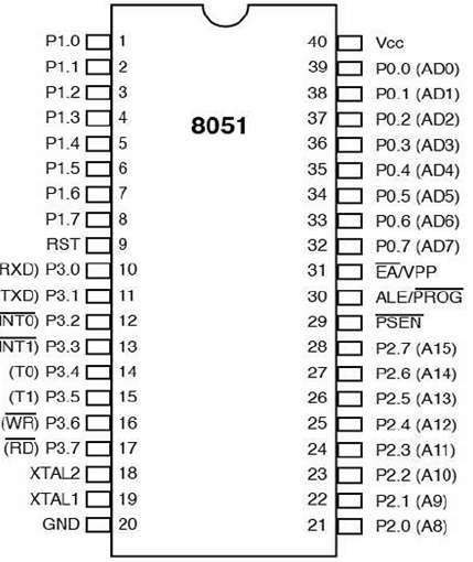
- The 8051 has 40 pins total, 20 on each side of the microcontroller (MCU), and is packaged in a Dual Inline Package (DIP). These 40 pins have all been designated for various uses and I/O operations such as serial connection, interrupts, and analog/digital read-write.

- Pins 1-8: These pins are known as port 1 pins and are employed for carrying out basic I/O activities. By setting these pins’ logic states to 0 or 1, you can configure them.
- Pin 9: The microcontroller can be reset via this pin, known as the RESET pin. This pin can be used to stop a microcontroller activity that is currently running.
- Pin 10-17: They are known as port 3 pins. Similar to port 1, port 3 pins serve as a universal input-output port in addition to performing a few additional tasks, which are detailed below.
- P3.0 (RDX): This serial pin is used to receive data. It is used to set up a serial connection so that data can be received via the input signal.
- P3.1 (TXD): Another serial pin is this one. It is utilized for data transmission over the serial port using the output signal.
- P3.2 and P3.3: External hardware interrupts are handled by these pins.
- P3.4 and P3.5 (T0 and T1): A 16-bit counter can be linked to these timer pins.
- P3.6: A memory write pin is used for writing information to external memory.
- P3.7: This pin is for reading data from external memory and is used for external memory.
- Pin 18 and 19: These pins can be used to link quartz oscillators to external oscillators to supply clock frequency.
- Pin 20: This is the ground (GND) pin used to link sensors and other modules with the microcontroller that has a GND (negative) line.
- Pin 21 to 28: This is the ground (GND) pin used to link sensors and other modules with the microcontroller that have a GND (negative) line.
- Pin29: The name of this pin is “Program Store Enable” (PSEN). It reads data from external memory.
- Pin 30: Known as Address Latch Enable, this pin (ALE ). It is employed to distinguish between addresses from different memory.
- Pin 31: External Input (External Access) input is the name of this pin. It is employed to turn on and off external memory interfacing.
- Pin 32 – Pin 39: These are pins for port 0. They serve as I/O ports and are also bidirectional.
- Pin 40 (VCC): It is a pin used to supply circuits with +5V of power.
Features & Specifications of Microcontroller 8051
- On-chip ROM of 4 KB (Program memory).
- 128-byte on-chip memory (Data memory).
- eight-bit data bus (bidirectional).
- sixteen-bit address bus (unidirectional).
- two timers in 16 bits.
- 1-microsecond instruction cycle with a 12 MHz crystal.
- 4 8-bit ports total.
- 128 flags set by the user.
- Four register banks, each with eight bits.
- RAM with a 16-byte bit address.
Applications of Microcontroller 8051
Despite the development of more advanced and better microcontrollers, the 8051 The microcontroller is still utilized in many embedded systems and applications.
- The following is a list of possible uses for 8051 microcontrollers.
- Consumer Electronics (TV Tuners, Remote controls, Computers, Sewing Machines, etc).
- Applications at Home (TVs, VCR, Video Games, Camcorder, Music Instruments, Home Security Systems, Garage Door Openers, etc).
- Systems for Communications (Mobile Phones, Intercoms, Answering Machines, Paging Devices, etc).
- Office (Fax Machines, Printers, Copiers, Laser Printers, etc).
- Automobiles (Air Bags, ABS, Engine Control, Transmission Control, Temperature Control, Keyless Entry, etc).
- Aviation and Space.
- Medical Supplies.
- Defense Mechanisms.
- Robotics.
- Control of industrial processes and flows.
- Equipment for Radio and Networking.
- Distance sensing.
