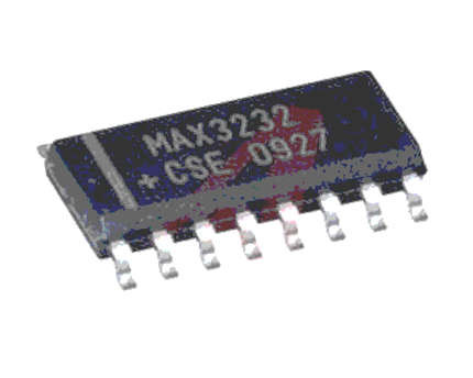
- The MAX3232 device consists of two line drivers, two line receivers, and a dual charge-pump circuit with ±15-kV ESD protection terminal to terminal (serial-port connection terminals, including GND).

- The device meets the requirements of TIA/EIA-232-F and provides the electrical interface between an asynchronous communication controller and the serial-port connector. The charge pump and four small external capacitors allow operation from a single 3-V to 5.5-V supply. The devices operate at data signaling rates up to 250 kbit/s and a maximum of 30-V/μs driver output slew rate.
- The MAX3232 transceivers have a proprietary low dropout transmitter output stage enabling true RS-232 performance from a 3.0V to 5.5V supply with a dual charge pump. The devices require only four small 0.1µF external charge-pump capacitors. The MAX3232 is guaranteed to run at data rates of 120kbps while maintaining RS-232 output levels.
Where to use MAX3232 IC
- MAX3232 is used for TTL/CMOS to RS232 conversion. Meaning most of our Microcontrollers (PIC/ARM/Atmel) operates on TTL/CMOS logic that communicates through either 0V or +5V, but our computers work with the help of RS232 which operates at logic level -24V or +24V. So, if we have to interface these microcontrollers with the Computer we need to convert the TTL/CMOS logic to RS232 logic.
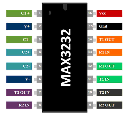
MAX3232 Pinout Configuration

- Pin 1 ( C1 + ) Connects to the positive end of the first capacitor.
- Pin 2 ( V + ) Connects to one end of the capacitor & the other end is grounded.
- Pin 3 ( C1 – ) Connects to the negative end of First Capacitor.
- Pin 4 ( C2 + ) Connects to the positive end of the second capacitor.
- Pin 5 ( C2 – ) Connects to the negative end of the second capacitor.
- Pin 6 ( V – ) Connects to one end of the capacitor & the other end is grounded.
- Pin 7 ( T2 OUT ) Transmission pin of second converter module for RS232 cable.
- Pin 8 ( R2 IN ) Reception pin of second converter module for RS232 cable.
- Pin 9 ( R2 OUT ) Reception pin of second converter module for Microcontroller(Rx).
- Pin 10 ( T2 IN ) Transmission pin of second converter module for Microcontroller(Tx).
- Pin 11 ( T1 IN ) Transmission pin of first converter module for Microcontroller(Tx).
- Pin 12 ( R1 OUT ) Reception pin of first converter module for Microcontroller(Rx).
- Pin 13 ( R1 IN ) Reception pin of first converter module for RS232 cable.
- Pin 14 ( T1 OUT ) Transmission pin of first converter module for RS232 cable.
- Pin 15 ( Ground ) Connects to the ground of the circuit.
- Pin 16 ( Vcc ) Connects to the supply voltage typically +5V.
How to use a MAX3232 Converter IC
- This IC is easy to set up and can be used easily. The IC works with the help of 3.3V/+5V, hence power the Vcc with the required voltage and the ground pin to circuit ground. The IC also needs four capacitors to work; these capacitors can be of any value from 1uF to 22uF.
- The IC can help you to convert two logic level conversions that you can use two Microcontrollers, but to get started we will use only one MCU and connect it to a computer, the complete circuit to do the same is shown below. As you can see the pins (T2 out, R2 in, T2 in, R2 out) are left free since we are not using the second module.
![]()
- Every microcontroller that has Serial communication capability will have a Tx pin and an Rx pin. These two pins should be connected to the T1 in (pin 10) and the R1 out (pin 13) pin respectively. These are the TTL/CMOS logic inputs, and then the converter RS232 logic signals can be obtained from pins R1 in (pin 13) and T1 out (pin 14). You might wonder how a 3.3V/5V signal is being converter to a +25V signal when the IC itself is powered with 3.3V/5V. This is made possible by a method called a charge pump, which consists of a capacitor that charges up to provide 25V.
Application of MAX3232 IC
- Used to Connect Microcontroller with Computers.
- TTL/CMOS logic to RS232 converters.
- Used in RS232 cables.
