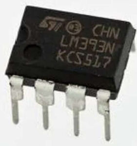
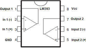
- This IC has two inbuilt operational amplifiers internally which are compensated with frequency.
- This is using a single power supply for performing their different task.
- It can work perfectly with split power supply sources.

Working of LM393 IC

- It consists of two inbuilt operational amplifiers (op-amp) and both op-amps used a single power.
- The power source connected with the Vcc and GND pins of the LM393 IC to activate the IC.
- Then the two input voltage provide to the op-amp for comparison and then we get the output from the op-amp.
- If the input voltage 1 > input voltage 2 then the output voltage is low (GND).
- If the input voltage 1 < input voltage 2 then the output voltage is high (VCC).
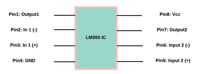
Pin Configuration

| Pin Name | Description |
|---|---|
| Pin1 | (OUTA): Output A |
| Pin2 | (In A-): Inverting input A |
| Pin3 | (In A+): Non-inverting input A |
| Pin4 | (GND): Ground |
| Pin5 | (INB+): Non-inverting input B |
| Pin6 | (INB-): Inverting input B |
| Pin7 | (OUTB): Output B |
| Pin8 | (Vcc): Voltage Supply |
Features of LM393 IC
- Single voltage supply ranges from 2.0 Vdc toward 36 Vdc.
- Split supply range will be from +1.0 Vdc or -1.0 Vdc to +18 Vdc or -18 Vdc.
- Little Supply Voltage of Current Drain Independent is 0.4 mA.
- The input bias current is low that is 25nA.
- Input offset current is low that is 5nA.
- Both the range of differential input, as well as Power Supply Voltage, are equivalent.
- The output voltage is well-suited by ECL, MOS, DTL, TTL, & CMOS Logic Levels.
Applications of LM393 IC
- It is used in Voltage Comparator circuits, Zero-Crossing detectors, Battery-Powered Applications, High Voltage protection/Warning, and Oscillator circuits.
- It Can be used to drive a Relay, Lamp, Motor Etc.
