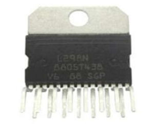
- This IC is used in the motor driver module to control the speed of the DC motor.
- A controller like Arduino provided the input to the motor driver module.
- Hence this logic is used to control the direction of the motor which is connected with the motor driver IC.
Pin Configuration
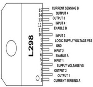
| Pin Name | Description |
|---|---|
| IN1 & IN2 | Motor A input pins. Used to control the spinning direction of Motor A |
| IN3 & IN4 | Motor B input pins. Used to control the spinning direction of Motor B |
| ENA | Enables PWM signal for Motor A |
| ENB | Enables PWM signal for Motor B |
| OUT1 & OUT2 | Output pins of Motor A |
| OUT3 & OUT4 | Output pins of Motor B |
| 12V | 12V input from DC power Source |
| 5V | Supplies power for the switching logic circuitry inside L298N IC |
| GND | Ground pin |
Working of L298N Motor Driver IC
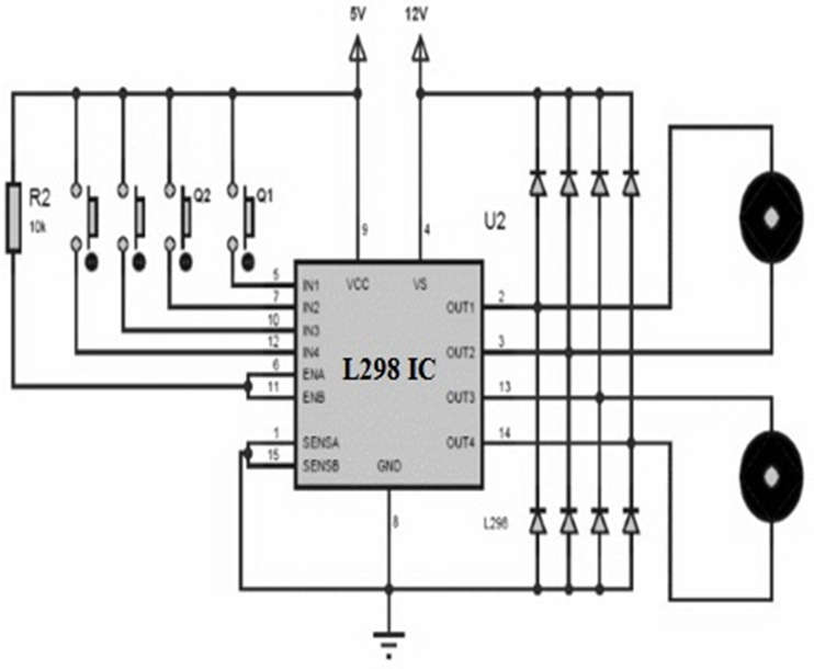
- If Q1 is high and Q2 is low then it is forward current.
- If Q1 is low and Q2 is high then it is a reverse current.
- When both the pushbuttons are equal like Q1=Q2 then it is a quick motor stop.
- The Q1 push button is pressed then the current start flowing from o/p1 to o/p2 means the motor rotated in a clockwise direction.
- Likewise, the Q2 push button is pressed then the current start flowing from o/p2 to o/p1 means the motor rotates in the anti-clockwise direction.
- When both buttons are pressed simultaneously or released then the motor will be stopped.
- So, the motor speed can be controlled through an L298 motor driver IC.
Applications of L298N Motor Driver IC
- This IC is used in different fields like robotics, embedded, etc.
- It is applicable where H- BRIDGE is used.
- This is used in high-power-based applications.
- Motor driver IC is used where current control & PWM operable IC is required.
- It is used where the control unit provides only TTL outputs.