

Neutral Earthing Resistors (NERs) are key parts of modern electrical power setups. They play a crucial role by limiting fault currents through the neutral point of transformers & generators. This helps in making operations safer. Testing NERs is a vital process to affirm their functionality and the overall reliability of the power system.

What is a Neutral Earthing Resistor?
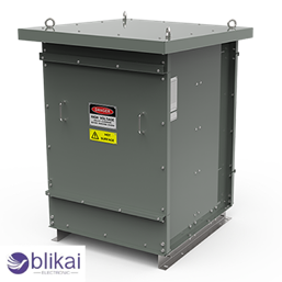
A Neutral Earthing Resistor (NER) is a resistor connected between the neutral point of a transformer or generator and the earth’s ground. It serves to limit fault currents in industrial and utility power systems. The resistor’s primary functions include reducing the magnitude of earth fault currents, thereby minimizing damages and facilitating quicker fault detection and isolation.

Key Parameters
– Resistance (Ohms): Defining the current limiting capability.
– Continuous Current Rating: The maximum fault current the NER can handle continuously.
– Voltage Rating: This should be appropriate for the system’s neutral voltage.
– Time Rating: Specifies the duration the NER can withstand fault currents.
Construction
NERs are typically constructed using materials like stainless steel, which offer high resistance and thermal stability. They are enclosed in robust housings to protect them from environmental factors.
Advantages of Neutral Earthing Resistors
- Fault Current Limitation: By limiting fault currents, NERs reduce the potential damage to equipment during ground faults.
- Improved Protection: They contribute to the protection of sensitive machinery by keeping fault currents within manageable levels.
- Enhanced Safety: Lower fault currents mean less severe arc flashes and reduced risk of electrical fires.
- Reliable Fault Detection: With limited fault current, protective relays can more accurately detect and isolate faults quickly.
How to Test a Neutral Earthing Resistor
Testing NERs involves several steps, from initial safety precautions to detailed electrical measurements.


Step 1: Safety Considerations
Personal Protective Equipment (PPE):
Before beginning the testing, ensure that all personnel involved are equipped with appropriate PPE, including:
– Insulated gloves and boots
– Safety glasses
– Flame-resistant clothing
System De-energization:
Ensure the system is de-energized:
– Open all upstream circuit breakers.
– Follow lockout/tagout procedures to prevent accidental energization.
– Verify the absence of voltage using a suitable testing device.
Step 2: Initial Visual Inspection
Physical Condition:
Conduct a visual inspection to identify any physical damage, corrosion, or burn marks on the NER and its connections. These can indicate potential areas of concern.
Connection Integrity:
Check that all electrical connections are tight and secure. Loose connections can lead to elevated resistance, resulting in inefficient fault current handling.
Nameplate Verification:
Ensure that the NER’s nameplate information matches the system requirements, including voltage rating, current rating, and specified resistance value.
Step 3: Insulation Resistance Testing
Purpose:
To ensure insulation is intact preventing unwanted leakage that could risk system safety.
Equipment:
– Insulation Resistance Tester (Megger)
Procedure:
- Disconnect the NER from the system.
- Connect the insulation resistance tester between the resistor element and the earth.
- Apply the test voltage (typically 500V to 5kV, depending on the system).
- Record the resistance value.
Analysis:
Acceptable insulation resistance values usually range in the megohms. A lower value indicates potential insulation faults, possibly due to moisture ingress or material degradation.
Step 4: Continuity and Resistance Measurement
Purpose:
This test verifies that the NER’s resistance is within the specified range, ensuring it will limit the fault current as designed.
Equipment:
– Digital Multimeter (Ohmmeter function)
Procedure:
- Ensure the NER is disconnected from the system.
- Connect the multimeter across the resistor terminals.
- Measure the resistance and note the value.
Expected Values:
The resistance should match the manufacturer’s specifications (typically in milliohms to a few ohms).
Step 5: Power Frequency Testing
Setup:
Power frequency testing involves applying a rated voltage at the normal operating frequency (50 Hz or 60 Hz) and measuring the resulting current to ensure the NER operates correctly under real conditions.
Equipment:
– AC Voltage Source
– AC Ammeter
Procedure:
- Ensure all equipment is calibrated correctly.
- Connect the NER to the AC voltage source and the ammeter in series.
- Gradually apply the rated voltage and monitor the current.
Analysis:
Compare the measured current to the theoretical value calculated using \( I = \frac{V}{R} \). Significant deviations may indicate issues such as partial shorts or incorrect resistor values.
Step 6: Temperature Coefficient Verification
Importance:
The resistance of materials can change with temperature. Verifying the temperature coefficient ensures the NER operates correctly under varying thermal conditions.
Procedure:
- Apply a controlled current to warm up the NER.
- Measure the resistance at various temperatures.
- Plot a resistance vs. temperature graph.
Analysis:
The resistance changes should align with the manufacturer’s specified temperature coefficient. Deviations might indicate material flaws or design issues.
Step 7: Reconnection and System Verification
Reconnection:
After testing, reconnect the NER to the system, ensuring all connections are properly secured.
Initial Energization:
Gradually re-energize the system, monitoring for any abnormal signs such as unusual heating, noise, or unexpected resistance values.
Full System Check:
Conduct a comprehensive system check to verify no new faults have been introduced and that all protective devices function correctly.
Step 8: Maintenance and Regular Testing
Importance of Regular Testing:
Periodic testing helps detect gradual performance degradation, allowing for timely maintenance and preventing unexpected failures.
Scheduling:
Integrate NER testing into routine maintenance schedules, adhering to manufacturer recommendations and safety standards.
Documentation and Trend Analysis:
Maintain detailed records of all test results and observations for trend analysis. Regular review helps identify patterns and inform future maintenance decisions.
Continuous Improvement:
Regularly review and update testing and maintenance procedures based on new insights, technological advancements, and manufacturer guidelines to ensure the highest safety and performance standards.
Conclusion
Testing a Neutral Earthing Resistor follows structured steps, ensuring system reliability and consistency. By following the guide, you perform tests to keep systems stable, avoiding unexpected breakdown failures.