

Imagine that you can control the electronic appliances of your home from anywhere inside the house, just using your Smart phone. In this project, we will use wireless Bluetooth technology to control the Home Electronic Appliances through a Android Phone. Bluetooth has a range of 10-15 meters, so that you can switch ON and OFF any electronic appliance within the range.
In this article, we are going to learn how to control Home appliances using the Arduino board and HC-05 Bluetooth module. Let us start with the Hardware requirements for the circuit.
Components Required –

- Arduino UNO
- Bluetooth module(HC-05)
- 16X2 LCD
- 12V Relay
- BC547 transistor
- 1K ohm resistor
- 5 mm LED
- 10K ohm PRESET
- Two pin plug
- Three pin holder
Mobile Command:
- Any Android phone
- Android app (Bluetooth terminal)
- Android app (BT voice Control for Android for voice commands)
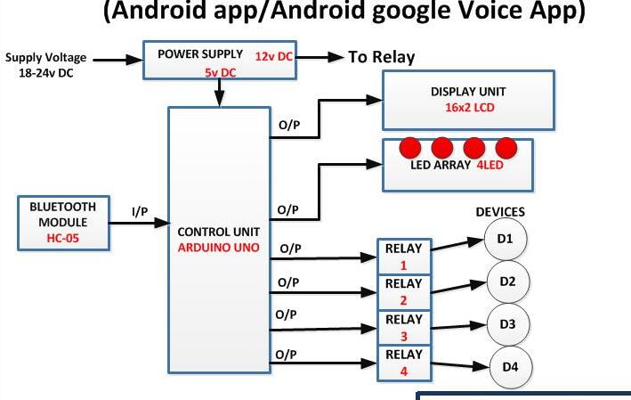
Block Diagram –
Block Diagram of Arduino based Home Automation System

Circuit Diagram –
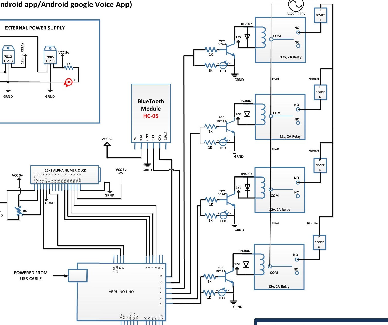

Circuit Connections –
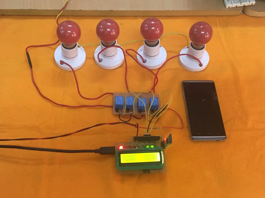
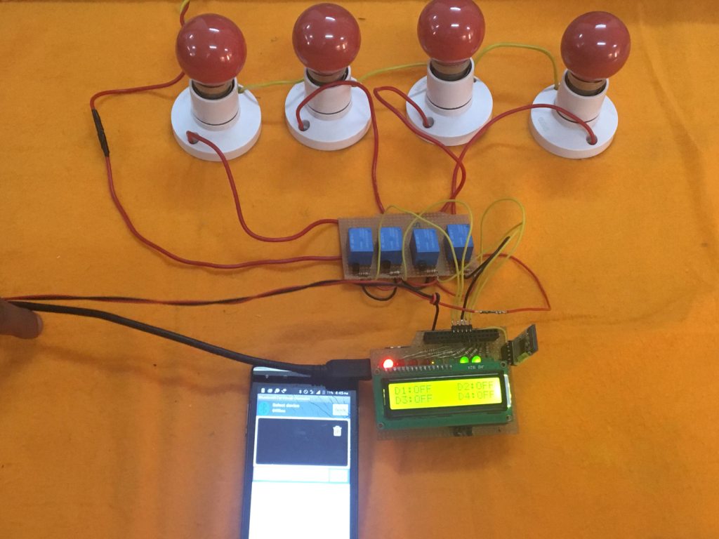
Prototype of Arduino based Home Automation System

The Arduino UNO is the master component of entire circuit and different components and modules are interfaced to it. The circuit has the following modules and components connected to the Arduino board
Power Supply:
In the circuit, Arduino board, LCD module and LEDs need a 5V regulated DC while relays need 12V regulated DC for their operation. A 18V battery is used as the primary source of power. The supply from the battery will be regulated to 5V and 12V using 7805 and 7812 ICs. The pin 1 of both the voltage regulator ICs will be connected to the anode of the battery and pin 2 of both ICs will be connected to ground. The respective voltage outputs will be drawn from pin 3 of the respective voltage regulator ICs. An LED along with a 10K Ω pull-up resistor can also be connected between common ground and output pin to get a visual hint of supply continuity.
16X2 LCD:
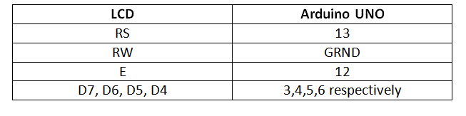
The 16X2 LCD display will be used to display the status of devices. It is connected to the Arduino board by connecting its data pins to pins 2 to 5 of the Arduino board. The RS and E pins of the LCD are connected to pins 13 and 12 of the Arduino UNO respectively. The RW pin of the LCD is grounded.
Table Listing Circuit Connections between Arduino Uno and Character LCD

The standard open-source library for interfacing LCD with Arduino UNO is used in the project. The library works as expected and needs no changes or modifications.
Relays:
The 12V 2A relays are used to switch the AC appliances ON or OFF in the project. The relays are connected to the pins 9, 8, 7 and 6 of Arduino board via BC547 transistor circuits connected in a common emitter configuration. The phase wire from the AC supply is provided at the COM terminal of the relays. When a HIGH logic is received at the interfaced microcontroller pins, the COM point switches from NC to NO point where a relay short-circuits the phase with the neutral wire switching the supply to the appliance ON. The LEDs are connected parallel to the relay circuit with pull-up resistors in series. These LEDs give visual hint of the ON/OFF status of appliances.
HC-05 Bluetooth Module:
The Bluetooth module has six pins – Enable, VCC, Ground, Transmit Data (TxD), Receive Data (RxD) and State. The Enable and State pin are unused and so not connected in the circuit. The VCC and Ground pins are connected to the common VCC and Ground. The TxD and RxD pins of the module are connected to the pins 10 and 11 of the Arduino.
How the project works –

When the circuit is powered on, the Arduino loads the required libraries and switches relays to OFF position. Some initial messages are flashed on the LCD display and the status of all the four devices is shown OFF on the LCD. The Arduino waits for the numeric command to be received from the Bluetooth module. The four appliances are assigned numbers from 1 to 4. If either number is obtained as a string from the Bluetooth module, the status of the respective appliance is toggled. By default, the pins connecting to the relays have a LOW logic driving the relays to switch the appliances OFF.
If an appliance is in OFF condition and number representing it is passed through the Bluetooth app, the Arduino switches the logic at the respective pin to HIGH triggering the relay to switch the appliance ON. The change in the status of the appliance is updated on the LCD display and the LED indicating supply to the appliance starts glowing due to forward biasing.
If an appliance is in ON condition and number representing it is passed through the Bluetooth app, the Arduino switches the logic at the respective pin to LOW driving the relay to switch the appliance OFF. The change in the status of the appliance is updated on the LCD display and the LED indicating supply to the appliance stops glowing due to lack of forward voltage.
The numbers are transferred to the interfaced Bluetooth module from the paired smart phone. The smart phone must be paired with the Bluetooth module. Either Bluetooth Terminal or BT Voice app can be used to pass the numeric commands.
Programming Guide –
First of all the Software Serial library for serial communication with the Bluetooth Module and Liquid Crystal library for LCD interfacing are imported. An object of the virtual serial type is declared and mapped to the pins where Bluetooth module is interfaced. An object of Liquid Crystal type is instantiated and mapped with the pins connected to the LCD module. A variable to hold Bluetooth command is declared and variables tracking status of the appliances are declared. The pins connected to relays are assigned to variables ONE, TWO, THREE and FOUR.

A setup() function is called in which the baud rate for serial communication with the Bluetooth module and the LCD module is set to 9600 bits per second using begin() method on the respective objects. The pins connecting relays are set digital output and initial messages are printed on the LCD.

The loop() function is called in which first it is tested if any serial data from the Bluetooth module is available. If it is available, it is read and stored in BTData variable. The value is BTData is compared to the numbers assigned to each appliance along with the status tracking variables and the status of the respective appliance is toggled accordingly in If-else decision making statements. The status of each device is updated on the LCD display by replacing the strings on the screen.

Note: The complete Arduino sketch for Bluetooth based Home Automation System can be found under the source code tab.
Project Source Code
###
//Program to
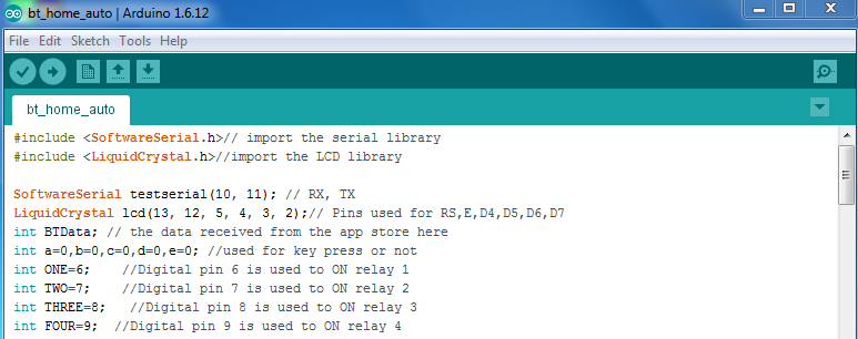
#include <SoftwareSerial.h>// import the serial library
#include <LiquidCrystal.h>//import the LCD library
SoftwareSerial testserial(10, 11); // RX, TX
LiquidCrystal lcd(13, 12, 5, 4, 3, 2);// Pins used for RS,E,D4,D5,D6,D7
int BTData; // the data received from the app store here
int a=0,b=0,c=0,d=0,e=0; //used for key press or not
int ONE=6; //Digital pin 6 is used to ON relay 1
int TWO=7; //Digital pin 7 is used to ON relay 2
int THREE=8; //Digital pin 8 is used to ON relay 3
int FOUR=9; //Digital pin 9 is used to ON relay 4
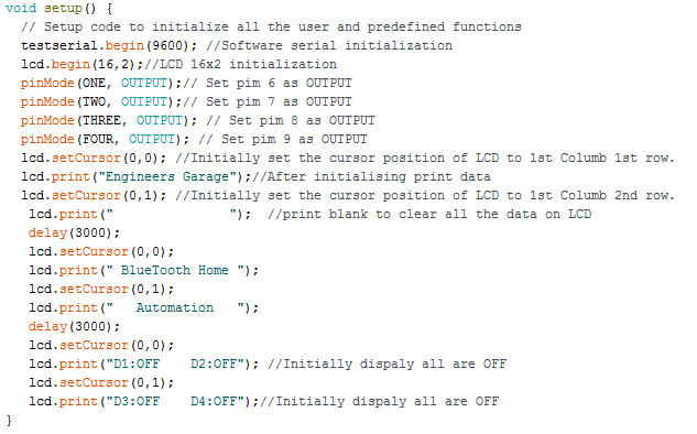
void setup() {
// Setup code to initialize all the user and predefined functions
testserial.begin(9600); //Software serial initialization
lcd.begin(16,2);//LCD 16x2 initialization
pinMode(ONE, OUTPUT);// Set pim 6 as OUTPUT
pinMode(TWO, OUTPUT);// Set pim 7 as OUTPUT
pinMode(THREE, OUTPUT); // Set pim 8 as OUTPUT
pinMode(FOUR, OUTPUT); // Set pim 9 as OUTPUT
lcd.setCursor(0,0); //Initially set the cursor position of LCD to 1st Columb 1st row.
lcd.print("Engineers Garage");//After initialising print data
lcd.setCursor(0,1); //Initially set the cursor position of LCD to 1st Columb 2nd row.
lcd.print(" "); //print blank to clear all the data on LCD
delay(3000);
lcd.setCursor(0,0);
lcd.print(" BlueTooth Home ");
lcd.setCursor(0,1);
lcd.print(" Automation ");
delay(3000);
lcd.setCursor(0,0);
lcd.print("D1:OFF D2:OFF"); //Initially dispaly all are OFF
lcd.setCursor(0,1);
lcd.print("D3:OFF D4:OFF");//Initially dispaly all are OFF
}
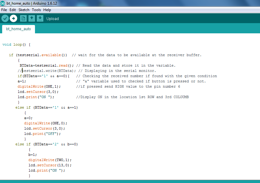
void loop() {
if (testserial.available()) // wait for the data to be available at the receiver buffer.
{
BTData=testserial.read(); // Read the data and store it in the variable.
//testserial.write(BTData); // Displaying in the serial monitor.
if(BTData=='1' && a==0){ // Checking the received number if found with the given condition
a=1; // "a" variable used to checked if button is pressed or not.
digitalWrite(ONE,1); //if pressed send HIGH value to the pin number 6
lcd.setCursor(3,0);
lcd.print("ON "); //Display ON in the location 1st ROW and 3rd COLOUMB
}
else if (BTData=='1' && a==1)
{
a=0;
digitalWrite(ONE,0);
lcd.setCursor(3,0);
lcd.print("OFF");
}
else if (BTData=='2' && b==0)
{
b=1;
digitalWrite(TWO,1);
lcd.setCursor(13,0);
lcd.print("ON ");
}
else if (BTData=='2' && b==1)
{
b=0;
digitalWrite(TWO,0);
lcd.setCursor(13,0);
lcd.print("OFF ");
}
else if(BTData=='3' && c==0){
c=1;
digitalWrite(THREE,1);
lcd.setCursor(3,1);
lcd.print("ON ");
}
else if (BTData=='3' && c==1)
{
c=0;
digitalWrite(THREE,0);
lcd.setCursor(3,1);
lcd.print("OFF ");
}
else if (BTData=='4' && d==0)
{
d=1;
digitalWrite(FOUR,1);
lcd.setCursor(13,1);
lcd.print("ON ");
}
else if (BTData=='4' && d==1)
{// if number 0 pressed ....
d=0;
digitalWrite(FOUR,0);
lcd.setCursor(13,1);
lcd.print("OFF ");
}
else;
}
delay(100);
}
###