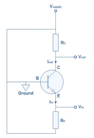
- The Common Base Amplifier is another type of bipolar junction transistor (BJT) configuration in which the transistor’s base terminal serves as a common terminal for both input and output signals, hence the name “common base” (CB). The common base configuration is less common as an amplifier configuration than the more popular common emitter (CE) or common collector (CC), but it is still used because of its unique input/output characteristics.
- The input signal is applied to the emitter terminal and the output is taken from the collector terminal for the common base configuration to function as an amplifier. As a result, the emitter current is also the input current and the collector current is also the output current; however, because the transistor is a three-layer, two PN-junction device, it must be correctly biased to function as a common base amplifier. That is, the base-emitter junction is biased forward.

- The common-base configuration is so named because (aside from the DC power source), the signal source and the load share the base of the transistor as a common connection point, as shown in the Figure below.
Common Base Configuration
- The image below depicts both NPN and PNP transistors in a common base configuration. The base terminal in the common base configuration is always at ground potential, regardless of the type of transistor.
![]()
- The input variables in the common base configuration are emitter current iE and base to emitter voltage VBE. The collector current iC and the base to collector voltage VCB are also output variables.
- Two sets of characteristics are required to fully describe the characteristics of a common base configuration such as a Common Base Amplifier.
- 1. Input Characteristics (aka Driving point or Transfer characteristics)
- 2. Output Characteristics (or collector characteristics)
- While the output variable VCB is held constant, the input characteristics will relate to the input variables, namely emitter current iE, and base to emitter voltage VBE.
![]()
- In terms of output characteristics, they will relate the output variables, namely collector current iC, and base to collector voltage VCB, while holding constant the input variable, emitter current iE.
![]()
Construction of Common Base Transistor Amplifier
- The amplifier circuit formed by a CB configured transistor combination is referred to as a CB amplifier.
- The common base amplifier circuit with an NPN transistor is shown below, with the input signal applied at the emitter-base junction and the output signal applied at the collector-base junction.
![]()
- VEE biases the emitter-base junction forward, while VCC biases the collector-base junction reverse. The operating point is set using the resistors Re and Rc. Thus, VCC, VEE, Re, and Rc determine the values of Ic, Ib, and Icb.
Working of Common Base Transistor Amplifier
- When no input is applied, the quiescent conditions are formed, and there is no output. Because Vbe is negative concerning ground, the forward bias for the positive half of the input signal is reduced. As a result, the base current IB is also reduced.
- As we know,
IC ≅ IE ≅ βIBIC ≅ IE ≅ βIB - Both the collector current and emitter current get decreased.
- The voltage drop across RC is
VC = ICRCVC = ICRC - This VC also gets decreased.
- As ICRC decreases, VCB increases. It is because,
VCB = VCC − ICRCVCB = VCC − ICRC - As a result, a positive half-cycle output is produced.
- A positive input produces a positive output in a CB configuration, so the input and output are in phase. In a CB amplifier, there is no phase reversal between input and output.
- The CB configuration has a low input impedance and a high output impedance when used for amplification. In addition, the voltage gain is low when compared to the CE configuration. As a result, CB-configured amplifiers are commonly used in high-frequency applications.
Characteristics of Common Base Transistor Amplifier
The Common Base amplifier circuit has the following characteristics.
- Gain in voltage is high.
- Current gain is low.
- Power gain is low.
- The phase relationship between input and output is 0o.
- The input impedance is low.
- It has a relatively high output impedance.
Applications of Common Base Transistor Amplifier
- When a low input impedance is required, the common base amplifier circuit is used. The common base amplifier circuit has the following applications.
- It is used in the preamplifiers of moving coil microphones.
- It is used in RF amplifiers for UHF and VHF frequencies.
