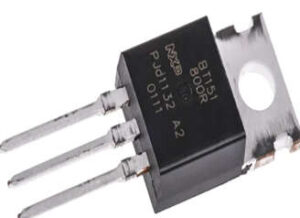
- Planar passivated Silicon Controlled Rectifier (SCR) in a SOT78 plastic package for use in applications requiring high bidirectional blocking voltage, high surge current, and high thermal cycling performance.
- The BT-151 is a power-switching SCR with a medium power rating. SCRs are similar to transistors, but they can latch, or stay on once triggered even if the gate signal is removed. They stay in conduction till the anode-cathode current drops below a certain value called the holding current. SCRs behave in many ways like diodes, with similar forward drops, thus the name ‘controlled rectifier.’

- The planar process is a semiconductor manufacturing process that is used to build individual transistor components and then connect those transistors. It is the primary method for producing silicon integrated circuit chips. Surface passivation and thermal oxidation are used in the process.
- In physical chemistry and engineering, passivation refers to coating material so that it becomes “passive,” or less easily affected or corroded by the environment. Passivation is the process of creating an outer layer of shield material that is applied as a micro coating, created chemically with the base material, or allowed to build naturally in the air.
- A silicon-controlled rectifier, also known as a semiconductor-controlled rectifier, is a four-layer solid-state current controller. General Electric’s trade name for a type of thyristor is “silicon controlled rectifier.”
- An SCR, like a diode, conducts when a gate pulse is applied to it. It has four layers of semiconductors that combine to form one of two structures: NPNP or PNPN. It also has three junctions labeled J1, J2, and J3, as well as three terminals: anode, cathode, and agate as shown below.
Circuit Diagram
Use of SCR in a DC circuit is shown in the circuit diagram below.
- The diagram above shows a simple example of a thyristor controlling a direct current load, such as a small direct current motor. The motor is connected to a 12V DC supply via the BT151 thyristor in this case, but it will not run until the thyristor is made to conduct. This is accomplished by briefly closing the ‘start’ switch, which sends a current pulse to the gate terminal of the thyristor. As the thyristor is turned on, the motor begins to run, and its resistance is very low.
- There is no longer any gate current when the start switch is returned to its normally open position, but the thyristor continues to conduct and the current continues to flow. The motor continues to run in a direct current circuit. Following operations on the start switch have no effect. Only if the current flow falls below the thyristor’s holding current threshold will the thyristor turn off.
- This is accomplished by briefly closing the stop switch, which shorts the thyristor. Because the SCR current is now less than the current holding value, the circuit current now flows through the stop switch rather than the thyristor, which instantly turns off. The motor could also be stopped by connecting a normally closed switch to the thyristor. When pressed, it would also temporarily stop current flow through the thyristor, allowing the thyristor to turn off.
Pin Configurations
The pin diagram of BT151 SCR is shown below.
- Cathode – The cathode emits conventional current.
- Anode – The anode receives conventional current.
- Gate – Controls the flow of current between the anode and cathode.
- Tab – Electrically connected to the anode.
| PIN | Description |
|---|---|
| 1 | cathode |
| 2 | anode |
| 3 | gate |
| tab | anode |
Application of BT151 SCR
- The BT151 thyristor is commonly found in ignition circuits, protection circuits, industrial and household lighting appliances, motor controllers, static switching, various solid-state relays for over-voltage protection, full-wave bridge rectification, half-wave rectification purposes, and other applications.
- SCRs are primarily used in devices that require high power control, possibly coupled with high voltage, below can be some of the applications where BT151 can be used.
-
- The silicon-controlled rectifier (SCR) is used in AC voltage stabilizers.
- The silicon-controlled rectifier (SCR) is used as a switch.
- It is used in choppers.
- The silicon-controlled rectifier (SCR) is used in inverters.
- The silicon-controlled rectifier (SCR) is used for power control.
- It is used for DC circuit breakers.