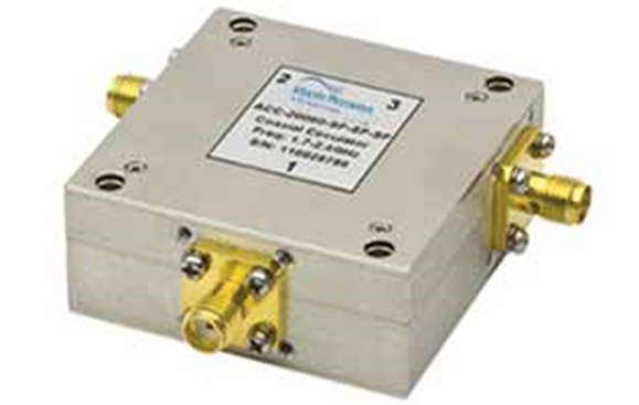
RF or microwave circulators are typically three port devices based on ferromagnetic materials that steer RF power from one port to another, isolating it from the others.

RF Circulator
- It is defined as a non-reciprocal, passive three-port, ferromagnetic device in which power is transferred from one port to the next adjacent port in a prescribed order.
Working Principle of Circulator

- The circulators are available in waveguide or stripline forms. Based on the direction of signal travel in the circulator two major types are clockwise circulator and anti-clockwise circulator.
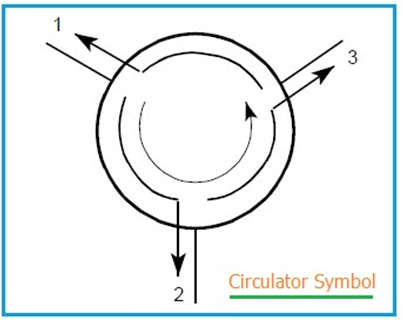
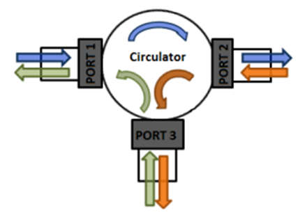
- The signal flows from port 1 to 2, from port 2 to 3, and from port 3 to 1. Therefore the signal input is port-1 will give out a signal from port-2 and there should not be any signal output from port-3 and so on.
- This is because insertion loss of circulator is loss from 1 to 2 which is very less.
- The loss from port-1 to port-3 is known as Isolation which is quite high.
- RF circulator becomes an Isolator when one of its ports is loaded with matched impedance.
- A Circulator utilizes a transversely magnetized ferrite junction to circulate incoming signal from port 1 to port 2, port 2 to port 3, and port 3 to port 1.
- The magnetic fields and the signal is represented with the direction of the arrow applied to any port of these devices.
- In the case of RF signal a low loss in the direction of the arrow and a high loss in the reverse direction while propagating through the Circulator.
- Such if a signal is placed at port 1 and port 2 is well matched, the signal will exit at port 2 with very little loss.
- If there is a mismatch at port 2, then some signal power will be reflected towards port 3.

Applications of Circulator
- It is used in Television & Radio Broadcasting, Radio links & telecommunication networks, Aviation & navigation industries, Military equipment & Radar systems, Laboratory measurement systems, and Industrial microwave heating.
RF Circulator & Isolator Specifications
- Frequency: A specific frequency range is required for RF circulators to function properly. The isolation between ports and directions that should not be linked as well as the achievable insertion loss set a limit on the frequency range.
- Although specialized (and expensive) versions can be constructed to function on bands between 100 MHz and 100 GHz, RF circulators typically operate between frequencies of around 750 MHz up to roughly 20 GHz.
- Every RF circulator will be able to function within a narrow band. Currently available examples include those that can work between 3 and 6 GHz, 7.9 and 8.4 GHz, and so on. Naturally, there are numerous other instances, many of which are created for particular RF circuit design applications for satellites, radar, etc.
- Impedance: A characteristic impedance must be set for each feeder and other electronic parts used in RF power transfer. 50 ohms is the most common impedance level for RF circulators.
- Insertion Loss: This is the attenuation of the incident signal, or attenuation in the forward direction, from one port to the next, measured in decibels (dB). Typical values could fall between 0.1 and 0.75 dB. The figure will vary depending on the circulator in question, its frequency range, and other elements.
- A circulator’s or isolator’s insertion loss often rises with frequency. To maintain the transmitted power at high power, choosing a circulator with the lowest loss will be especially crucial. At higher powers, there will be more circulator loss, therefore choosing one that can manage the required power is crucial.
- Isolation: The attenuation in the reverse flow direction, measured in n dB, is shown in this number. It normally ranges from 17 to 35 dB. Two RF circulators can be connected in series if higher levels of isolation are required.
- Power Handling: Where high power levels are required, the power handling standard for RF circulators is especially crucial. It is crucial that these limits are not exceeded since the wiring and ferromagnetic materials can only tolerate a certain amount of power. Otherwise, performance may suffer or the component may suffer irreparable damage. dBm, dB, or Watts are commonly used to measure power levels.
- Package Type: Circulators come in a wide range of packaging options. They typically come in connector-equipped manufacturer-standard packages, while there are other formats available as well, such as drop-in and surface mount.
- Connectors: The type of connector is crucial for RF circulators that have connectors. SMA and N-type connectors are two of the most often used varieties. When space is at a premium and power levels are modest, SMA is the best option, whereas N-type is better for higher power levels. It should be kept in mind that SMA connectors can manage remarkably large power levels on their own.
- VSWR: The voltage standing wave ratio, or VSWR, shows how well the impedance level is matched to the necessary level. Typically, VSWR levels between 1:1.2 and 1:1.5 are attained.
