Phase locked loops, PLLs are a key RF circuit building block, but they often appear to be shrouded in mystery. Find out how they work.
- It is an electronic circuit with a voltage or voltage-driven oscillator that constantly adjusts to match the frequency of an input signal.
- It is used to generate, stabilize, modulate, demodulate, filter, or recover a signal from a “noisy” communications channel where data has been interrupted.
- A PLLs is a closed-loop feedback control circuit that’s both frequency- and phase-sensitive.
- It is not a single component, but a system that contains analog and digital components — interconnected in a “negative feedback” configuration.

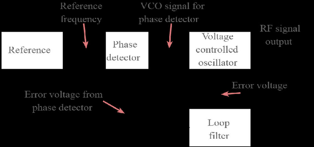
- The above shows the block diagram of a phase locked loop, and the reference signal and the signal from the voltage-controlled oscillator are connected to the two input ports of the phase detector.
- The output from the phase detector is passed to the loop filter and then the filtered signal is applied to the voltage-controlled oscillator.
- The VCO is a voltage-controlled oscillator, within the PLL that produces a signal which enters the phase detector.
- Here the phase of the signals from the VCO and the incoming reference signal is compared and a resulting difference or error voltage is produced.
- This corresponds to the phase difference between the two signals.

Phase Locked Loop, PLL Applications
- FM Demodulation: One major phase locked loop application is that of an FM demodulator. With PLL chips now relatively cheap, these PLL applications enable high-quality audio to be demodulated from an FM signal.
- AM Demodulation: It can be used in the synchronous demodulation of amplitude modulated signals. Using this approach, the PLL locks onto the carrier so that a reference within the receiver can be generated. As this corresponds exactly to the frequency of the carrier, it can be a mixer with the incoming signal to synchronously demodulate the AM.
- Indirect Frequency Synthesizers: Use within a frequency synthesizer is one of the most important phases of locked-loop applications. Although direct digital synthesis is also used, indirect frequency synthesis forms one of the major phases of locked-loop applications.
- Signal Recovery: The fact that the phase-locked loop can lock to a signal enables it to provide a clean signal, and remember the signal frequency if there is a short interruption. This phase-locked loop application is used in several areas where signals may be interrupted for short periods, for example when using pulsed transmissions.
- Timing Distribution: Another phase locked loop application is in the distribution of precisely timed clock pulses in digital logic circuits and systems, for example within a microprocessor system.
