- One type of electronic amplifier called an audio amplifier is used to amplify electronic audio signals with low power, such as the output signal from a radio receiver. These amplifiers can be used in a variety of sound systems, including guitar amplifiers, home theatre systems, surround-sound systems, audio systems, and entertainment centers. The audio amplifier is the final electronic stage before the signal is sent to the loudspeakers in a conventional audio playback chain. Any audio source, including CD players, record players, cassette players, and digital audio players, can be plugged into the audio amplifier. The majority of amplifiers employ low-level inputs. For instance, the electric guitar signal is the input signal to an audio amplifier. This signal measures a hundred microwatts and generates a few watts which are used in small electronic devices like clock radios, a stereo systems used in homes, etc. This article discusses an overview of the MD8002A Audio Amplifier.
What is MD8002A Audio Amplifier?
- The MD8002A is a specific type of audio power amplifier that uses a 5V DC power source to continuously produce 2.0 watts of power to a BTL load with less than 10% distortion. It is specifically made to provide high-quality o/p power while utilizing fewer parts. It does not make use of output coupling or bootstrap capacitors.
- Through a specific pop-click removal circuit, this amplifier is excellently suited for low voltage applications as well as audio speakers. In switch-on and switch-off situations, these amplifiers give perfect pop-click characteristics. This amplifier has external gain-setting resistors and is unity-gain stable.
Pin Configuration of MD8002A Audio Amplifier
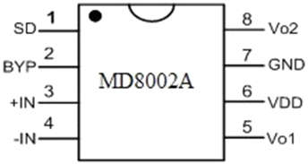
The pin configuration of the MD8002A Audio Amplifier includes 8 pins which are discussed below.

- Pin1 (SD): This is a Shutdown Pin. Active high.
- Pin2 (BYP): This is a bypass capacitor pin.
- Pin3 (+IN): This is a +Ve i/p pin of the initial Amplifier.
- Pin4 (-IN): This is a -ve pin of the initial amplifier.
- Pin5 (VO1): This is a negative o/p.
- Pin6 (VDD): This is a +ve Supply Pin.
- Pin7 (GND): This is a ground pin.
- Pin8 (VO2): This is a +ve output pin.
Features of MD8002A Audio Amplifier
The main features of the MD8002A audio amplifier include the following.
- It is capable of being configured for an outside benefit.
- It comes in the SOP8 Package.
- It is reliable for a single gain.
- It doesn’t require any bootstrap capacitors, o/p coupling capacitors, or snubber networks.
- An improved circuitry system eliminates pop-click sounds during turn ON and turns OFF conditions.
Specifications of MD8002A Audio Amplifier
The main specifications of the MD8002A audio amplifier include the following.
- The range of supply voltage is 2V to 6V.
- The o/p Power is 3W.
- The shutdown current is 0.6µA.
- The load impedance of audio is 3 Ohms.
- The improved PSSR is 60 dB at 217 Hz and 1kHz.
Equivalent & Alternative IC’s
The equivalent and alternative ICs of this amplifier include the following.
- An equivalent ICs of MD8002A audio amplifier is LM4871 and TDA2050.
- Alternatives ICs of MD8002A audio amplifier are AD620, LM386, JRC45558 & IC6283.
Where to Use?
- This kind of amplifier includes a function similar to a shut-down mode. This IC’s primary goal is to provide output power with good quality while utilizing fewer components. This amplifier does not require capacitors, as would happen in the absence of output coupling. It is utilized in low-voltage applications and audio speakers. For those seeking a dual op-amp IC with wide bandwidth and strong gain, this IC is the ideal option.
MD8002A Audio Amplifier Circuit
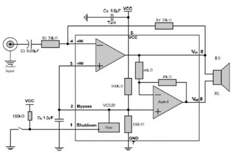
- Below is a diagram of this audio amplifier’s circuitry. Two operational amplifiers with various configurations can be used to construct this circuit. The primary op-gain amps can be adjusted externally, while the internal gain of the second amplifier’s inverting arrangement is set at unity.

The main components used in this circuit are Ri, Ci, Rf, Cf, and Cb which are discussed below.
- The gain of closed-loop conjunction is set by an inverting input resistance (Ri) through feedback resistance (Rf). The input coupling capacitor (Ci) and this resistor can be used to create an HPF (high pass filter) using the formula fc = 1/(2Ri*Ci).
- An input coupling capacitor (Ci) blocks the DC voltage at the amplifier’s i/p termination. Additionally, it develops an HPF by applying Ri to Fc = 1/(2Ri*Ci).
- The closed-loop gain is fixed by the feedback resistance (Rf) in conjunction with Ri. As a result, the gain is AVD=2*(Rf/Ri).
- The supply bypass capacitor (Cs) provides the power supply’s filtering.
- The bypass pin capacitor (Cb) provides half-supply filtering.
- While another amplifier’s gain can be controlled by the two internal resistors, the primary op-closed-loop amp’s gain can be fixed by selecting the ratio of Rf & Ri. The circuit shows that the output of the first amplifier is used as an input for the second amplifier, which produces signals that are 180° out of phase in magnitude.
Maximum Ratings
- The supply voltage ranges from-0.3V to 6V.
- Input voltage ranges from -0.3V to VDD+0.3V.
- Junction Temperature ranges from -40℃ to +150℃.
- Storage Temperature ranges from -65℃ to +150℃.
Operating Ratings
- The range of temperature is-40℃ ≦ TA ≦ 85℃.
- The supply voltage is 2.2V ≦ VDD ≦ 5.5V.
Applications of MD8002A Audio Amplifier
- Audio speakers.
- Audio Systems with Low Voltage.
- Audio Systems.
- Desktop Computers.
- Portable Computers.
