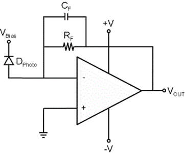
- Transimpedance amplifier is simply a current to voltage amplifier. Transimpedance comes from the term ‘transfer impedance’. In electronics, a trans-impedance amplifier (TIA) is a current-to-voltage converter, almost exclusively implemented with one or more operational amplifiers.
- The transimpedance op amp circuit configuration converts an input current source into an output voltage. The current to voltage gain is based on the feedback resistance. The circuit can maintain a constant voltage bias across the input source as the input current changes which benefit many sensors.
- It is also called a trans resistance amplifier as it functions the same as a resistor.
- The transimpedance is given as the ratio of the output voltage to the input current. Here we are dividing output voltage by input current, which gives the unit of resistance, and then the term trans-impedance can be used for the gain of such amplifier. For example, if a trans-impedance amplifier has a gain of 20ohms we can say that it has a trans-impedance of 20 ohms.
Working of Transimpedance Amplifier
- The transimpedance amplifier is just an inverting amplifier with negative feedback through the feedback resistor Rf.

- As we know that the input current of an Op-Amp will be zero due to its high input impedance, hence the current from our current source has to completely pass through resistor R1. Let’s consider this current as Is.
- But practically Op-amp will have some stray capacitance across its input ports which result in unnecessary output drifts and oscillations making the whole circuit unstable.
- To tackle this issue, instead of a single passive component, two passive components are used for the proper working of the Transimpedance circuit. Those two passive components are the feedback resistor (Rf) and a feedback capacitor (Cf). Both the resistor and the capacitor parallel between the amplifier’s negative input and the output as shown in the above figure.
- The operational amplifier here is again connected in negative feedback condition through the resistor R1 and the capacitor Cf as the feedback. The current (Is) applied to the Inverting pin of the Transimpedance amplifier will be converted into an equivalent voltage on the output side as Vout. The value of the input current and the value of the resistor (Rf) can be used to determine the output voltage of the Transimpedance amplifier.
- The output voltage also depends on the feedback capacitor and to calculate the value of this capacitor a formula is defined as,
Cf = 1/2π x R1 x fp
where
Rf = feedback resistor
fp = required bandwidth frequency
Applications of Transimpedance Amplifier
- They are sometimes used to further process the current output of photodiodes, pressure transducers, accelerometers, and other types of sensors to a voltage formatted as useable signal output.
- These amplifiers can also be used in some of the light sensing-related operations for the current signal measurement tool.
- Transimpedance amplifiers provide simple linear signal processing with an op-amp & a resistor to dissipate current.
- It is used in Optical equipment, Low-power analog sensors, RF equipment, Geiger–Müller tubes, Other kinds of sensors, Photomultiplier tubes, Photodetectors, and Accelerometers.
- TIAs are used in receivers of optical communication.
