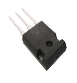
- The 2SA1943 is a semiconductor device that amplifies or switches electronic signals and electrical power. It is typically made of semiconductor material and has at least three terminals for connecting to an external circuit.
- A voltage or current applied to one pair of terminals of the transistor controls the current through another pair of terminals. A transistor can amplify a signal because the controlled (output) power can be greater than the controlling (input) power. Some transistors are still packaged individually today, but many more are embedded in integrated circuits.

- Now we know what is a PNP transistor but to understand how the 2SA1943 work and where to use it we need to take a short overview of what is a PNP power transistor.
- The power transistor, as the name suggests, is intended to operate at high power levels. That is, it can withstand high voltage and current.
- A power transistor has a completely different structure and construction than a signal transistor, but their characteristics and operation are nearly identical.
![]()
- It operates in four regions based on the forward and reverses bias conditions of the power transistor.
- Cut off region.
- Active region.
- Quasi saturation region.
- Hard saturation region.
- When an NPN power transistor is connected in reverse bias, the power transistor enters cut-off mode.
- Case 1: The negative terminal of a power transistor is connected to the base, and the positive terminal is connected to the emitter.
- Case 2: The collector is connected to the transistor’s negative terminal, and the positive terminal is connected to the transistor’s base terminal.
- In this case, the output current to the transistor’s base IBE = 0 and the output current flowing through the collector to the emitter IC = IB = 0. A small amount of leakage current flows from collector to emitter through the transistor.
- The transistor is said to be inactive when the collector-base region is reverse biassed and the base-emitter region is forward biased. When IB rises, IC rises as well.
- The collector-base and base-emitter connections of a transistor are connected in a forward bias pattern during the quasi saturation stage. When the collector-base and base-emitter are connected in a forward bias pattern, a hard saturation condition is achieved.
Pin Configurations
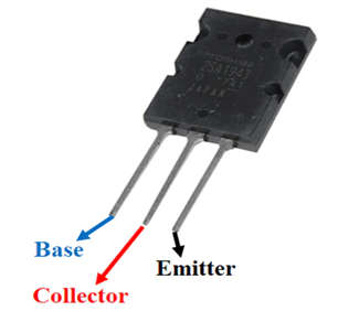
- The pin diagram of the 2SA1943 PNP Power transistor is shown below.

-
- Base – Controls the biasing of the transistor; used to turn the transistor ON or OFF.
- Collector – Current flows in through collector, normally connected to load.
- Emitter – Current Drains out through emitter, normally connected to ground.
Features and Specifications of 2SA1943 PNP Power Transistor
- power PNP Transistor
- DC Current Gain (hFE): 55 to 160
- Continuous Collector current (IC): 15A
- Collector-Emitter voltage (VCE): 230 V
- Collector-Base voltage (VCB): 230V
- Emitter Base Voltage (VBE): 5V
- Recommended for 150-W high-fidelity audio frequency amplifier output stage
- Maximum Operating Temperature: 150 C
- Mounting Style: Through Hole Medium
- Available in To-264 Package
Applications of 2SA1943 PNP Power Transistor
- Audio frequency Amplifier
- AF /RF circuits
- Low Slew rate devices
- Push-Pull configuration circuits
- high current switching (up to 15A) loads
- Can be used as medium Power switches
