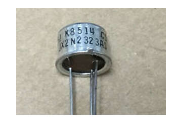
- 2N1595 is a Thyristor (or SCR) solid-state semiconductor device (Silicon Controlled Rectifier). It is a low-current industrial device in a three-lead package that is ideal for printed-circuit applications.
- This thyristor is typically used in low voltage AC rectifying, RMS voltage controller, and AC rectifier-based applications. At 100°C junction temperature, this thyristor has a current handling capacity of 1.6 A.

- We need to understand the basic working of a thyristor or SCR to understand the 2N1595 thyristor device working and where it can be used. So what is a thyristor?
- Thyristors, like transistors, are switching devices in general. It is a four-layered, three-junction semiconductor switching device. It is composed of three terminals: anode, cathode, and gate. Thyristors, like diodes, are unidirectional devices that only allow current to flow in one direction.
- As it has four layers, it is made up of three PN junctions connected in series. The gate terminal is used to trigger the SCR by applying a small voltage to it, which is also known as the gate triggering method.
![]()
- The silicon wafer in a thyristor is doped with four alternate P and N types, resulting in two transistors connected back-to-back (as seen in the pic above).
- The P (cathode) and N (anode) are connected in series here, yielding three terminal pins: anode, gate, and cathode.
- When we forward bias the anode and cathode, which are connected to the positive and negative terminals of a battery, the first and last PN junctions (j1 and j3) become forward biased due to the depletion layer breaking. Because no current is supplied to the gate, the junction j2 remains reversed-biased.
- When we apply current to the gate, the j2 junction layer breaks and current flows through the circuit. A sufficient positive signal current or pulse applied to the gate terminal causes the thyristor to enter the conducting state.
- A thyristor can only be fully on or off, unlike transistors, which can alternate between On and Off states. As a result, a thyristor is ineffective as an analog amplifier but useful as a switching device.
Pin Configurations
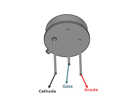
- The pin diagram of the 2N1595 Thyristor is shown below.

-
- Cathode
- Gate
- Anode
Features and Specifications
- Body case suitable for heat sink mounting.
- 50V maximum reverse blocking voltage.
- Peak repeat current handling capability of 1.6 amps at 125°C.
- High dependability.
- Temperature range of the operating junction: -65oC to +125oC.
- Temperature range for storage: -65oC to +150oC.
- Non-RoHS (Sn/Pb plating) options are available.
- 15A peak surge current.
- 0.1A is the maximum gate current.
- Time to turn on: 0.8S.
- Time to turn off: 10s.
- 10V peak gate voltage.
Applications of 2N1595 Thyristor
- It can control a large current and is commonly used as a high frequency switch in an electrical circuit.
- It is used in inverters, AC drives, induction heaters, and other applications.
- It is also used in SMPS, motor control, induction heating, etc.
- It may be found in relay-replacement circuits, oscillator circuits, level-detector circuits, chopper circuits, light-dimming circuits, low-cost timer circuits, logic circuits, speed-control circuits, phase-control circuits, and many other applications.
